
We no longer make these boards sorry !
Thanks for all your interest over the years but unfortunately we are no longer making these boards. All the Eagle plans are available and BOM’s below so you can make your own.
This is what you got :

They were supplied assembled with headers, RJ45 connector, LCD brightness pot, all capacitors, resistors and transistors soldered up. You don’t get the LCD, switches, LED’s or a case of course! The PCB is designed to fit into a Hammond 1598BSGYPB enclosure (Farnell 1426554). Personally I don’t use switches but these are suitable : Multicomp Momentary PTM
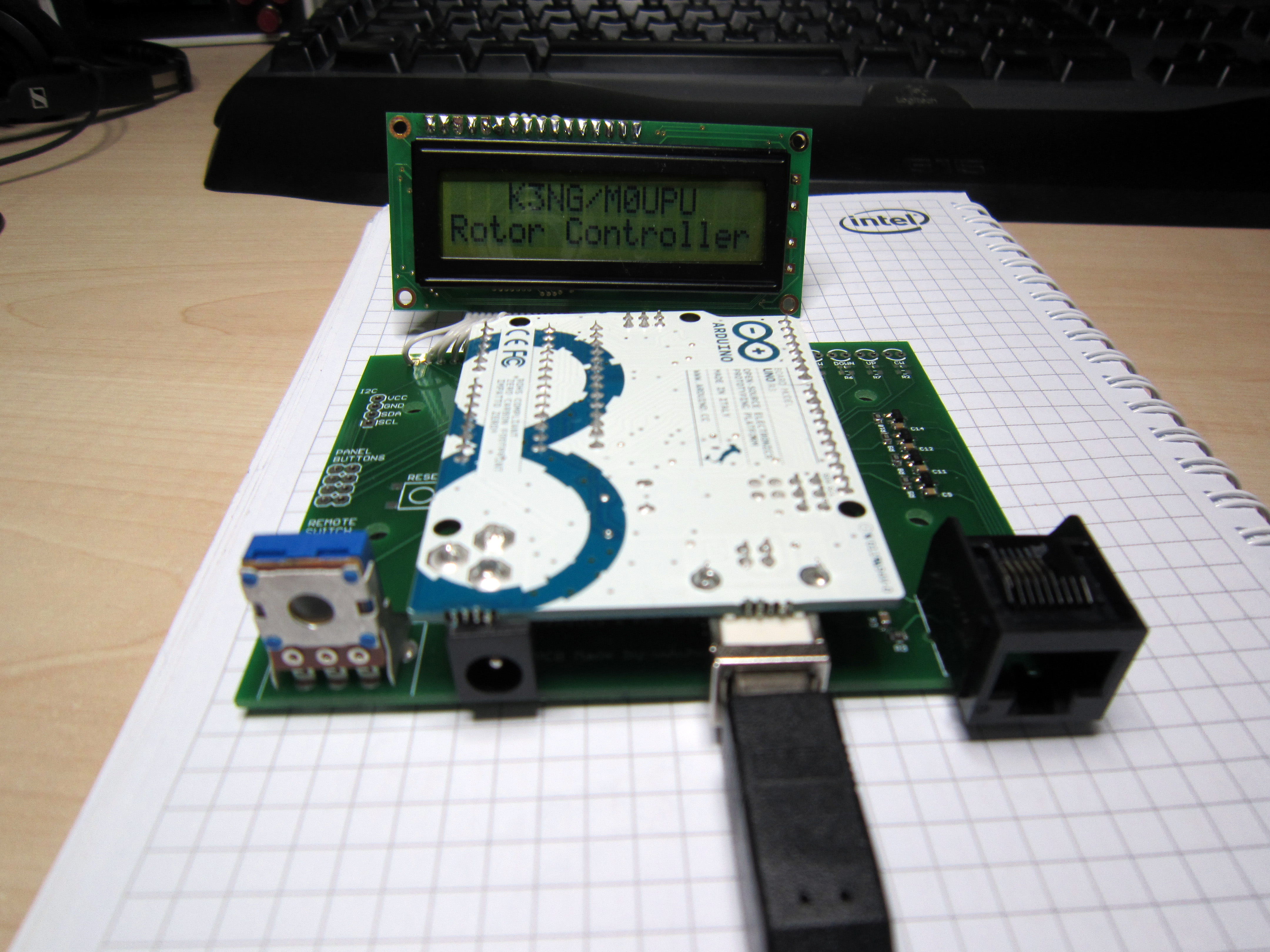
Here it is with an Uno installed :
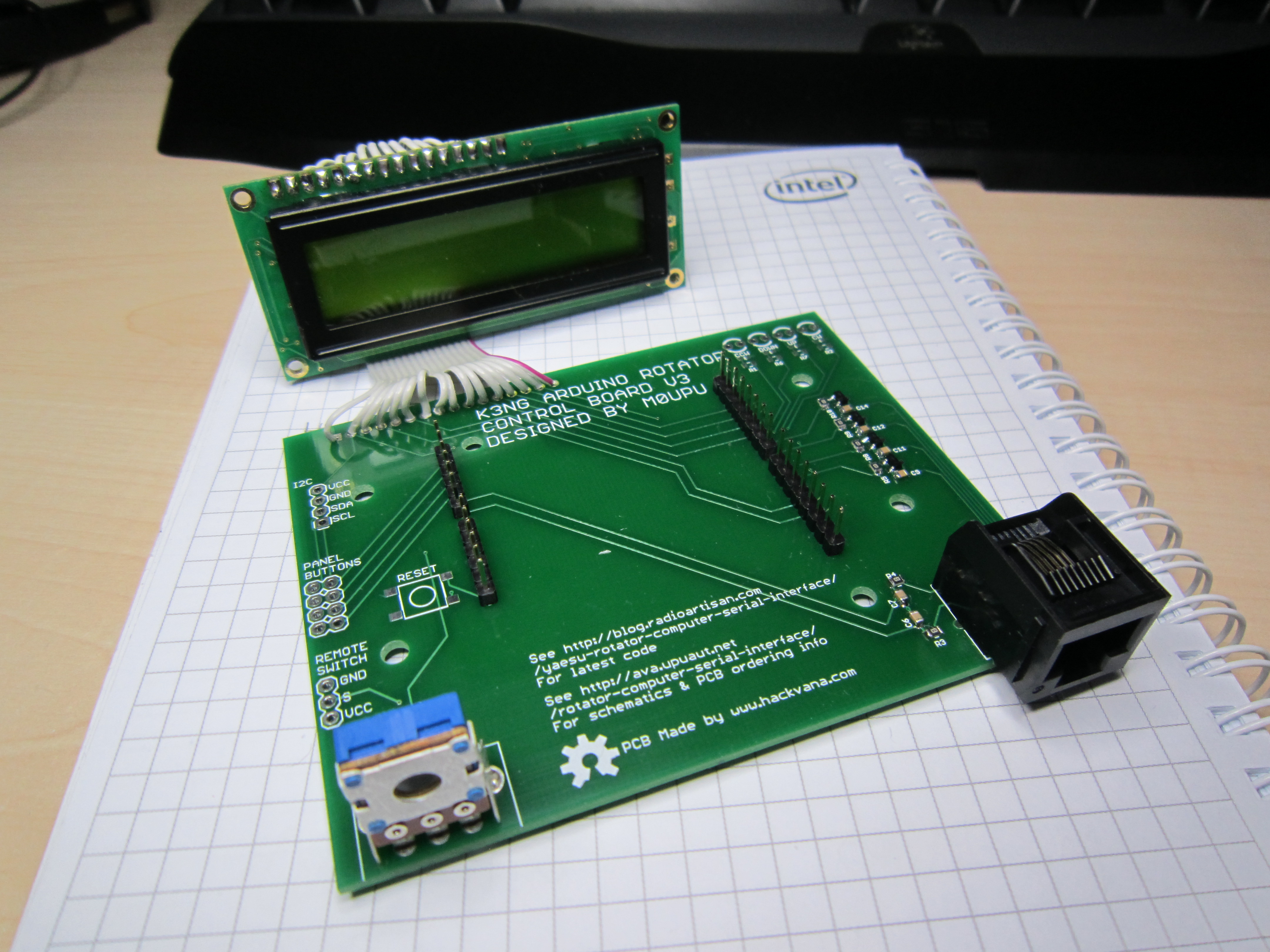
And without :
Update 29/05/2017 :
We are no longer making this board. It was the last board we made by hand and we no longer have the resources to do this. Unfortunately its not viable at the price to get this board made externally therefore we are discontinuing it.
Update 05/05/2013 :
I’ve sold out of the first two batches of these rotator boards so I’ve placed an order for some new ones which should be delivered before the end of May. We took the opportunity to add a few improvements to the PCB. Its still based round the concept of plugging an Arduino Uno or Duemilanove in upside down as per the post below. Additionally we added the following improvements :
1/ LCD back light is linked to a PWM port so you can adjust the LCD back light brightness via code.
2/ Reset switch added.
3/ Added a remote power switch port (I use this to power a relay to turn the controller on see http://ava.upuaut.net/?p=461
4/ Broke out the I2C Ports
5/ Added LED indicators for the axis activations.
6/ Redesigned the board to accommodate changes.
As before I plan to offer this PCB with the headers (RJ45 for rotator connection, Arduino headers and back light dimming resistor) and the switching circuits pre-assembled for about £25 including delivery (will confirm in the next few weeks).
You will need to supply reset switch/LED/LCD if you require these. Personally I use https://www.sparkfun.com/products/709 for the LCD.
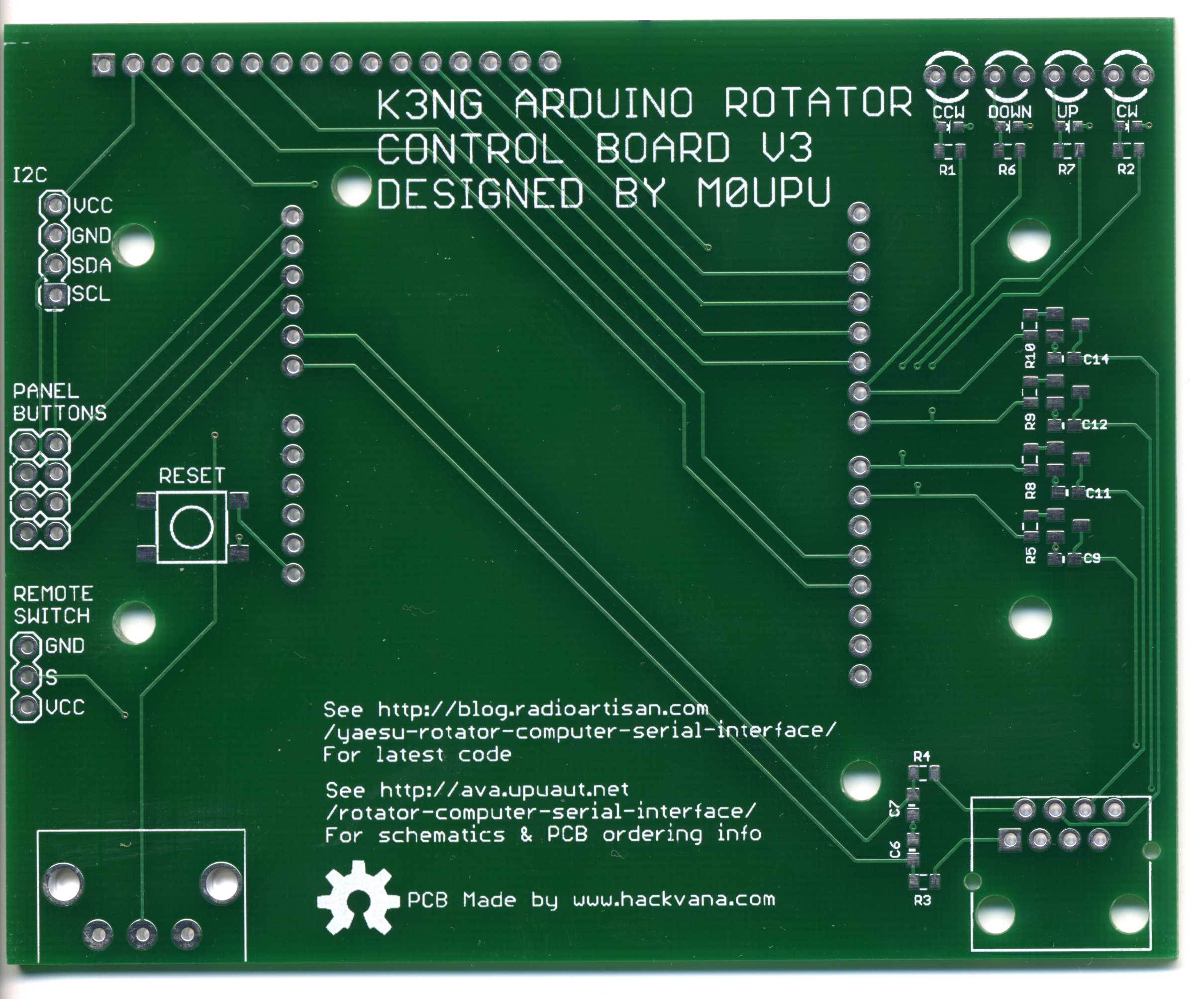
This design has been released as open source the schematic is available for download here : K3NG Rotator Interface V3, the Cadsoft Eagle files here : K3NG Rotator Interface V3. Using the schematic and this image :
You should be able to wire a cable to match your particular rotator controller.
Original Article :
Given my ideal location for tracking on top of a hill I decided last year to beef up the Watson Collinear antenna I was using to a yagi. The only issue with this is the yagi antenna is directional and needs to be pointed at the target. To facilitate this I purchased a Yaesu G-5500 Elevation-Azimuth Rotator unit. This comes with a great controller that has a port on the back to plug in the optional GS-232A controller.
The only downside is the controller is a few hundred quid which given it can be emulated with an Arduino seemed a little bit excessive. Having spent a while searching round the web I came across K3NG’s Arduino Rotator Serial Interface which was by far and away the most complete code I’ve seen.
These days making PCB’s is so cheap thanks to Mitch at Hackvana I decided to make a board for the rotator controller hardware. Initially I was going to make a custom Arduino board with AVR on it etc but then I decided to make it easy and just put a header on there so you could plug an Arduino Uno/Duemilanove on there. This instantly gives you power, the serial interface and is replaceable quite easily.

For the other components I used surface mount 0805 components and transistors. Connection to the rotator was via a CAT5 socket. The large pot on the left is to adjust the screen brightness. The header at the back is to connect an LCD too and there are 4 headers for physical up/down/left/right switches on there.
The Arduino goes in upside down :

Then the LCD plugs in :

Finally it was designed to go in a Hammond enclosure :

Add a 3D printed front bezel :

And voila a nice tidy interface for the controller that costs a damn sight less than the proper Yaesu thing. Now use K3NG’s wonderful code at http://radioartisan.wordpress.com/yaesu-rotator-computer-serial-interface/ to get it up and working.
I’ve released this board as Open Hardware so you are free to use it as you see fit. The Eagle CAD files are here : K3NG Rotator Interface V2
Bill of Materials for the board as follows :
Resistors : all 0805 1K Farnell 9332383
Capacitors : all 0805 0.1µF Farnell 1759143
Transistors : all MMBT2222A Farnell 9846700
RJ45 Jack : TE CONNECTIVITY 3-5338556-1 Farnell 2059819
Pot : TE CONNECTIVITY / CITEC 5350500107 Farnell 1174451
Header : Just buy strips of 1 row 2.54mm pitch header i.e Multicomp MC34743 Farnell 1593425
Case : Hammond 1598BSGYPBK Farnell 1426554
Just a quick warning I did originally intend to have the ICSP header broken out so you can program it via this but I didn’t have my spatial awareness hat on when I made the board and the lines are inverted so as it stands the ICSP break out isn’t usable (unless you plug it in from the rear of the board). This won’t affect you programming the Arduino as normal via the USB.
Hi,
Thanks for the sharing.
Is it possible with this interface to control the rotator from the pc via the USB connection on the arduino uno board? I don’t get the use of the RJ45 jack here.
Thanks for any help. 😀
Hi there thanks for your query. The RJ45 connector is there to connect the rotator to the Arduino board. From there you do indeed control the rotator via the USB. Basically using K3NG’s software (http://radioartisan.wordpress.com/yaesu-rotator-computer-serial-interface/) and this hardware and you have a Yaesu G232B clone.
Cheers,
Anthony
Do you still happen to have a board or two and components that you’re willing to part with? 🙂
Hi do you have any of the parts and PCB available for the rotator controller?
73 Clive GW0PPO
Dear Anthony,
First of all, Thank you very much for this super arduino rotor shield .
If you have still some board left , I am ready pay your cost + Shipping and would like to get one of them.
73 TA2LE
Do you have any pcbs left? I really want this but I am on a shoe string budget.
Thanks 73’s KA2RRZ
What kind of switches are those? You didn’t say if they were momentary or what, and you didn’t even list them in the materials.
Hi?have you any PCB for sale?Please?e-mail me
731RX3M
Hi how do I purchase a yaesu rotor controller board? Regards Terry
Hi there, do you have any boards left and if so how can I get one?
cheers
VK2BO
I would like a board. Please contact me.
Thank you and 73,
Don – KM0R
Hi,
Can someone let me know how you go about ordering one of K3NG pcb’s.
Peter
Hi Anthony,
If you still have boards for sale could you please send me an email with the address to send money
great project
Regards
Lee
hi,could you tell me if it is possible to management 2 rotors u-110 alliance by tenna rotors,for az & el without their controllers? and is possible to buy finished interface mounted with case and 4 swithces??
pse send me prices for eventual finished interface with case and pre-mounted board
Hi Anthony,
Have you any Rotator Controller boards left?
I like the look of this new version.
Peter GW4JOG
Hi Gianluca,
I’m not sure about managing two rotators, best to mail the Radio Artisan mailing list here : http://groups.yahoo.com/group/radioartisan/
I don’t sell the boards in case unfortunately sorry!
Anthony M0UPU
Hi Anthony
Great project, have master and slave working on bench for 10 Ghz az el dish mount on side of tower using satellite positioners tracking about 160 degrees az and 25 degrees el. Still have get az sensor working. One of these boards would be great to finish controller. Please send me an email on availability and payment
Cheers
David VK5KK
Thanks for a great description and design. I have always wanted to have a rotor control for satellite portable work using a compact, lightweight antenna such as the Arrow. ( I don’t want to hold the antenna!)
I am still looking for a low cost construction project for the mechanical rotor as the Yaesu rotors are too costly and have been made to handle more loads than I will ever need.
Dave, AA6RE
Hi Anthony, do you have any Rotator controller boards left and if so how can I get 2 of them?
regards, jac
Thanks for the board, and here are just a few quick thoughts…
1) Need to document the RJ45->G5500 cable pinouts
2) IF you ever do another version it might be nice to add an overlap LED as has been added to the code recently.
3) Also if another version is made, a STOP button and PARK button also might be nice.
Morning WS4E,
Many thanks for the feedback (always great to have some !). Bad timing on this one as I sent another 25 boards away for manufacturer two days before I got this mail, otherwise I would have added the features below. I was under the impression the Uno/Duemilanovo/Leonardo were out of pins anyway but I will review the design if I sell this next batch of 25. But :
1/ RF45 pin out follows normal CAT5 pin outs. The schematic is buried in the original post :
http://ava.upuaut.net/wp-content/uploads/2012/10/K3NG-Rotator-Interface-V3.pdf
So with this : http://www.cscape.net/images/standardmod.gif you should be able to wire for any rotator you choose to plug into it (I’ll add this to the article)
2/ Thats pretty easy and I’ll add this to the next revision.
3/ Generally that’s dealt with in software as by definition people are linking these to a PC. Personally I use PST Rotate. However its a fairly quick addition if there is a spare I/O pin on the board (this I’m not so sure about)
Again many thanks for the feedback its much appreciated.
Regards,
Anthony
Great looking design, but do you have the file for the 3D printed bezel? We’d love to have it to make it a complete project. Thanks.
Hi Jake,
https://dl.dropboxusercontent.com/u/63720513/Sketchup%20Models/AS_Faceplate_3.skp is the one I used but the mounting points are wrong and I ended up just gluing the LCD in place with hot glue.
Cheers,
Anthony
Anthony, How do I get one or two of your boards? I grabed the code this morning and compiled. Now I need a board. Thanks for all your work.
73,
Dave – NZ6D
:wq
Hello,
I’m interested to buy you a PCB. How can I do it if you have got any?
Best 73
Nicolas – F8FKD
Hi is this something you still have available ?
Thanks
Hi Anthony,
Are these kits still available ?
Hi Daren,
Certainly just click the Buy it now link at the top of the article. Cheers
Hi Stu,
Certainly just click the Buy it now link at the top of the article. Cheers
Can you elaborate on how I control the LCD brightness via “a PWM” port?
Also, I’m trying to get the latest K3NG code from github to compile.
I see that there are some M0UPU-specific things, and it looks like I should
#define HARDWARE_M0UPU
Is that right?
Even with that I’m getting a compile error, and the documentation leaves a bit to be desired.
Hi David,
I believe that to be the case. If its not compiling you may want to ask on the Radio Artisan mailing list giving details of the error it comes up with.See http://blog.radioartisan.com/support-for-k3ng-projects/
Sure this code never made it across to K3NG’s code and as a result isn’t supported by them.
Add
#define lcdbacklight 10
int fadeValue = 64;
In setup add :
analogWrite(lcdbacklight, fadeValue);
Thats it.
Cheers!
Hi Anthony,
got your PCB and code from the K3NG site. Software isn’t really my bag so I’m sure I’ve done something wrong as only getting black rows on the LCD. Have you got a copy of the code that is just for your board implementation? Would it be possible to email this if you have?
73
Malcolm G0UHY
There is no difference in the code from K3NG and mine for driving the LCD but you are welcome to it.
https://www.dropbox.com/s/ju2vrz8oklnkr5o/Rotator_Controller_20130128_UPU.ino?dl=0
Use at your own risk (elevation axis *may* be reversed)
Cheers
Hi Anthony,
Just to let you know the board arrived today. Very quick delivery and a nice quality board, now to compile the code.
73
Hi,
Looking at the board, if I want to use a backlight it has to be controlled by PWM via pin 10. I cannot get any of the code to work using this method as there are way to many compile errors for me to work through (I am a hardware guy). The standard K3NG code compiles fine.
I tried Anthony’s suggestion above but adding the extra lines but no luck.I also tried #define HARDWARE_M0UPU option but that will not compile either and neither does the .ino from the link Anthony provided.
Has anyone got a working code tree with the PWM backlight code they could share please.
73
Hi,
Just an update..
I now have the current K3NG code with your backlight additions compiled and working. I added:
#define lcdbacklight 10
Then in the “void setup” section I had to add both these lines for it to compile:
int fadeValue = 64;
analogWrite(lcdbacklight, fadeValue);
73
🙁
I’m new Arduino programming and only understand the very basics. I purchased the “UNO” version and have Arduino 1.65
and have tried to download and compile the programming but it will not compile. I keep getting errors like this
………………………………………………………
Arduino: 1.6.5 (Windows 7), Board: “Arduino Uno”
Build options changed, rebuilding all
Using library EEPROM in folder: C:\Program Files\Arduino\hardware\arduino\avr\libraries\EEPROM
Using library LiquidCrystal in folder: C:\Program Files\Arduino\libraries\LiquidCrystal
Using library Wire in folder: C:\Program Files\Arduino\hardware\arduino\avr\libraries\Wire
Using library SPI in folder: C:\Program Files\Arduino\hardware\arduino\avr\libraries\SPI
Using library Ethernet in folder: C:\Program Files\Arduino\libraries\Ethernet
C:\Program Files\Arduino\hardware\tools\avr/bin/avr-g++ -c -g -Os -w -fno-exceptions -ffunction-sections -fdata-sections -fno-threadsafe-statics -MMD -mmcu=atmega328p -DF_CPU=16000000L -DARDUINO=10605 -DARDUINO_AVR_UNO -DARDUINO_ARCH_AVR -IC:\Program Files\Arduino\hardware\arduino\avr\cores\arduino -IC:\Program Files\Arduino\hardware\arduino\avr\variants\standard -IC:\Program Files\Arduino\hardware\arduino\avr\libraries\EEPROM -IC:\Program Files\Arduino\libraries\LiquidCrystal\src -IC:\Program Files\Arduino\hardware\arduino\avr\libraries\Wire -IC:\Program Files\Arduino\hardware\arduino\avr\libraries\SPI -IC:\Program Files\Arduino\libraries\Ethernet\src C:\Users\Alex\AppData\Local\Temp\build1809726221472828370.tmp\k3ng_rotator_controller.cpp -o C:\Users\Alex\AppData\Local\Temp\build1809726221472828370.tmp\k3ng_rotator_controller.cpp.o
k3ng_rotator_controller.ino:8:30: fatal error: rotator_hardware.h: No such file or directory
compilation terminated.
Error compiling.
………………………………………………………
Any help would be really appreciated by a real newbie………
Hi ALex,
Looks like Arduino IDE sillyness there, try an older version of the Arduino program. If you get no where try the Radip Artisan mailing list.
Cheers,
Anthony
Hi,
What do you think about adding Motor Driver Shield für Arduino in order to directly drive the rotor without using the provided Yaesu controller.
73 Tzetzo
Could be done I think depends which motor shield. Its not something I’m personally going to do, could get complex!
Hello, I am putting together a paper for the USA East coast VHF convention based on your board and remember when researching this that I came across a page from someone that shows the common rotators and where to connect the boards based on the K3NG designs to the wires inside the control boxes for the different rotators. As much as I search I cannot find it again. Any ideas where it can be found?
Dorry I don’t have have you tried on Anthony Good’s K3NG Radio Artisan mailing list/site ?
Hello, does the I2C connections on the PCB connect to the HMC5883L 3-axis digital compass?
hi Anthony,
i have a G400rc do you have ready made units as soldering isn’t what it was and the price
The units I sell are pre-soldered up but I don’t sell any in a box ready to go ones if that’s what you mean. You’ll still need to case it and add an Arduino sorry!