
A number of people have asked for some more technical details on the AVA tracker hardware. The full name for the board is PAVA/ATLAS and it is a prototype based on my existing PAVA boards developed with the help of James Coxon, Phil Heron, Nigel Smart, Ed Moore and Dave Akerman.
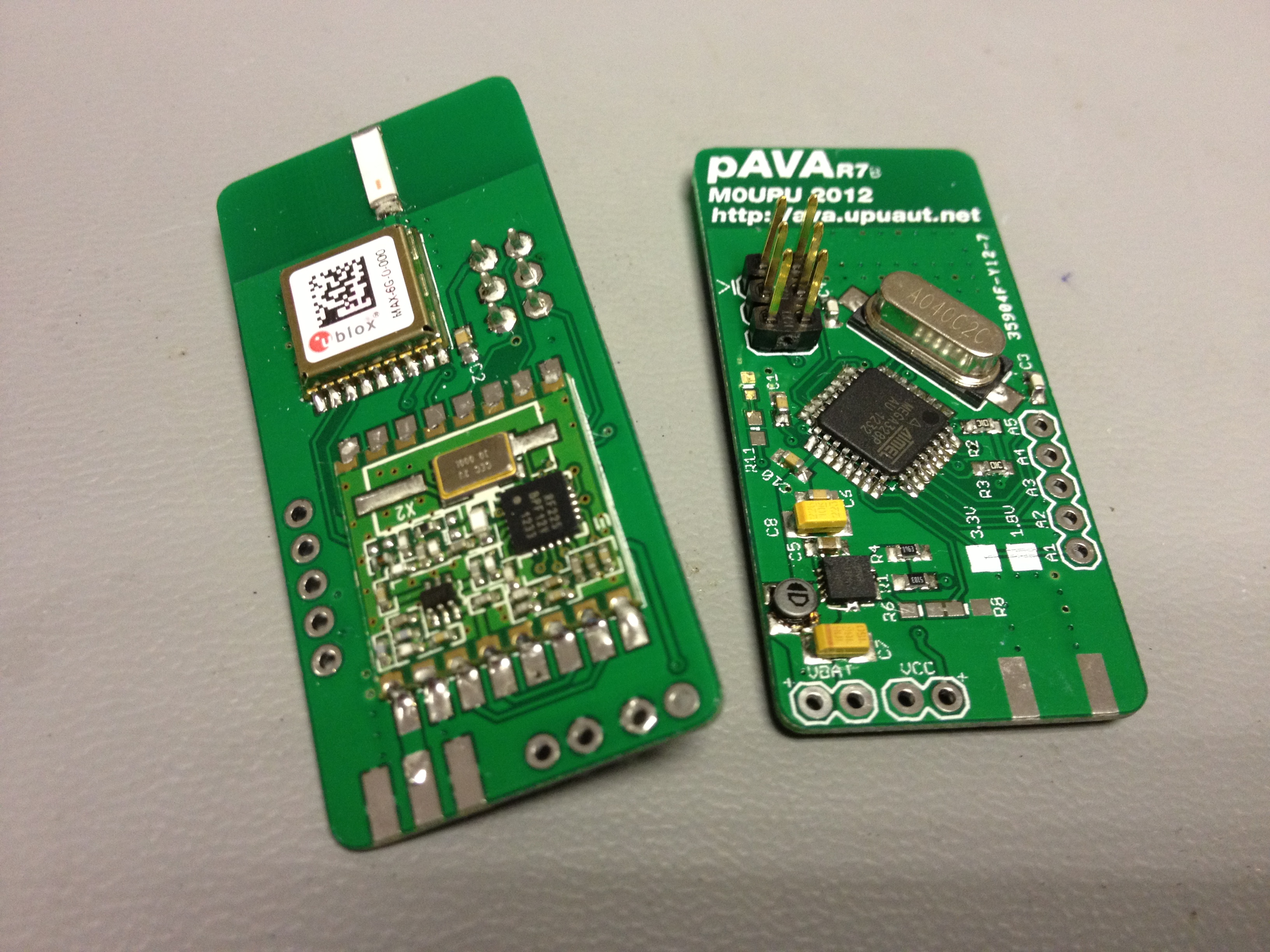
PAVA is a 70cms tracker board based on an ATMega328P Microcontroller, Ublox MAX6 GPS and a HopeRF RFM22B radio module. PAVA was born from a desire to make a tracker small enough and power efficient enough to be run from a single battery for enough time for a flight and possibly to reside in the neck of a balloon. To facilitate the use of the single cell a Texas TPS61200DRC boost converter is used.
The board was designed to initially run at 3.3v but have the option for running at 1.8v for increased power savings. 3.3v boards use a TPS61201 with a 0R0 in place. 1.8v boards use a TPS61200 with a 510k / 197k resistors to set the voltage. When running at 1.8v the AVR uses a 4Mhz crystal, 3.3v uses an 8Mhz crystal. Extensive work was done on the software and with a combination of the 1.8v hardware and the power saving in code the battery life was increased from 11 hours to about 47 hours.
A combination of the the hardware and software meant the PAVA boards were a very light, robust and good base for future projects.
PAVA/ATLAS was born out of Project Swift. The Swift board was a powerful but large board designed to do concurrent APRS transmissions outside of UK airspace and transmit RTTY telemetry as well. Although a good board there were a number of issues with Swift, namely the power requirements, weight and cost. James Coxon proposed a light weight version that could do the same but potentially under a foil balloon.
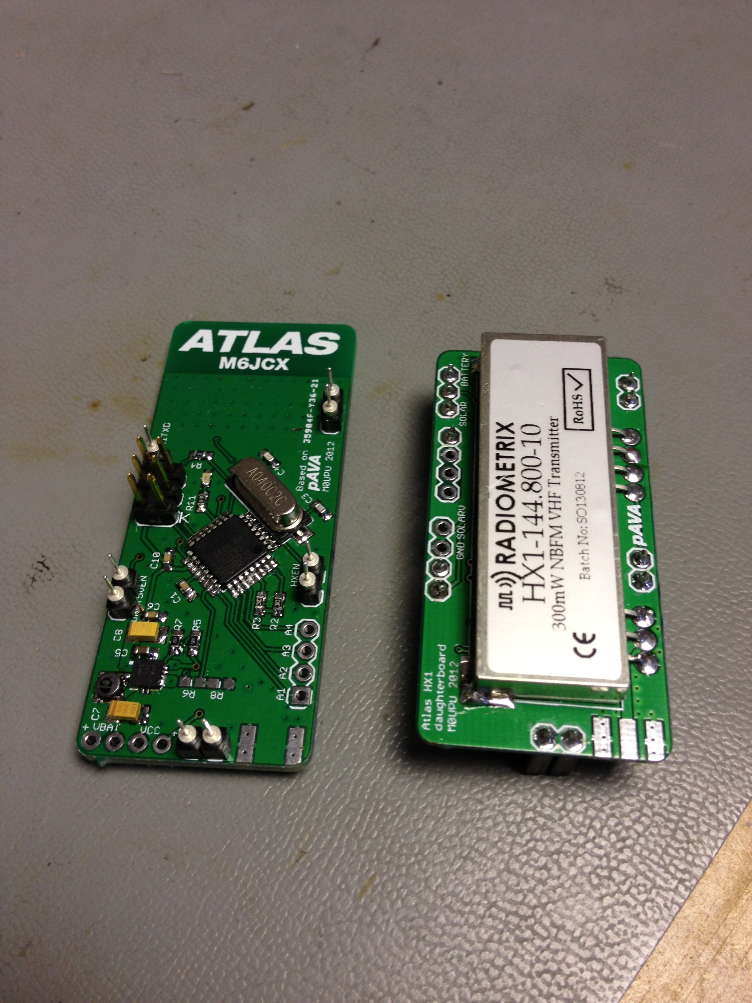
Taking the existing design for the PAVA boards a modified version was made to facilitate mounting a Radiometrix HX1 transmitter piggy back on it. Retaining the existing 1.8v board additional features were added, the GPS was wired to the batteries for hot starts. The GPS has a FET based power switch so it could be turned off entirely. The HX1 was mounted on a separate mezzanine board.
With its own 5V step up that could be switched on and off from the AVR it only needed to be on when transmitting then it was turned off again. To get the voltage up to the right level a transistor was used. The HX1 board mounted on top of the microcontroller board. To ensure the GPS antenna wasn’t obscured by the HX1 the board was extended slightly.
The board is very prototype and there are a number of errors on it :
a) RFM22B must be pulled down not up. This is fairly easy to fix as SDN is right next to GND so you can bridge it with a 0603 10k.
b) HX1TXD pin fouls the ICSP header. This was just a stupid mistake, you end up bending the pin to get the programmer on.
c) Holes for the Samtec headers are too large.
d) A polygon priority mistake left VBATT connected to GND. Pretty much a show stopper fixed with some careful scalpel surgery.
e) HX1 APRS TXD is on pin 11 which is use by the RFM22B. Cut the track and rewired it to the other interrupt pin 3.
Microcontroller board on the left, HX1 board on the right:
Underside (RFM22B & GPS to be attached)
The board weighed in at 16g and could run for way over 24 hours from a pair of AA’s with the APRS transmitting every 2 mins.
Hardware is only half the story. To comply with the UK legislation the APRS transmitter could not be used in the air (this also applies to other countries in the EU). Taking geofencing code from Project Swift & work done by Steve Randall a map of Europe was built up using Google Earth ( See this map ) and converted to code. See this post for more info: Preparing for a European Floater.
Once the payload knew where it was it could disable the APRS transmitter to comply with the local legislation. Additionally it could generate the correct ITU prefix for the callsign. This code was tested on two PAVA flights without the APRS module attached to iron out any bugs. The first test indicated the UK Geofence wasn’t correct.
The code use is here : https://github.com/Upuaut/APRS_Projects/tree/master/Pico92
The board will probably be redesigned as a single PCB.
Hi Anthony, is PAVA/ATLAS board already on market?
Is really “a 70cms tracker” or 7cms?
thanks
Michele
Hi Anthony
Great project, keep us updated about the new redesign. I´m very interested in build something like this for my car.