
With the end of life notification for the RFM22B I have been working on a replacement for the pAVA R7 Tracker for a while now. I decided to get away from the RFM22B style modules as they didn’t offer very much flexibility and the quality can be dubious. I wanted to fit the RF chip with a TCXO to prevent drift at colder temperatures.
My initial stab at it pAVA R8 was fitted with a step up and had a number of faults with it :
 It tested a few new ideas I had. Firstly the AVR Crystal, I’ve not found very small crystals in 4Mhz or below so I fitted an extremely small 16Mhz crystal and set the fuses to DIV/8 so the AVR runs at 2Mhz and therefore within the specs for running at 1.8V. This worked, however the SI4060 circuit I’d missed a few critical wires off, the board was also a total pig to solder. In total I made two by hand. Fixes were applied using Kynar wire to fix the missing SI4060 connections.
With some assistance from Arko using some code KT5TK developed for the SI4464 the tracker code was re-written to work with the SI4060 radio. This turned out to be a great success. The tracker supplied a solid and stable RTTY. On the 10th of November I strapped it to the bottom of a 36″ foil and launched it. The tracker performed flawlessly, sadly the balloon didn’t and at 6km altitude the balloon burst and dropped the tracker near Ridington. Leo Bodnar drove up in the dark but the landing site was inaccessible, he got a few positions from the tracker which looked like it was in a tree. See the KML for flight path.
Taking what I’d learnt and some inspiration from Leo Bodnar, I redesigned the board. The 16Mhz crystal with the DIV/8 worked so that was kept. The SI4060 circuit worked, however I wanted to open up the more interesting data modes like DominoEX. Leo suggested even though it was totally out of spec a 16.369Mhz crystal would give a minimum step size on the SI4060 of (FCrystal/2^21) = 7.805Hz. The step size for DominoEX16 is 15.625Hz so 2 x step = 15.61Hz which is close enough (Thx to SP3OSJ for maths lesson!)
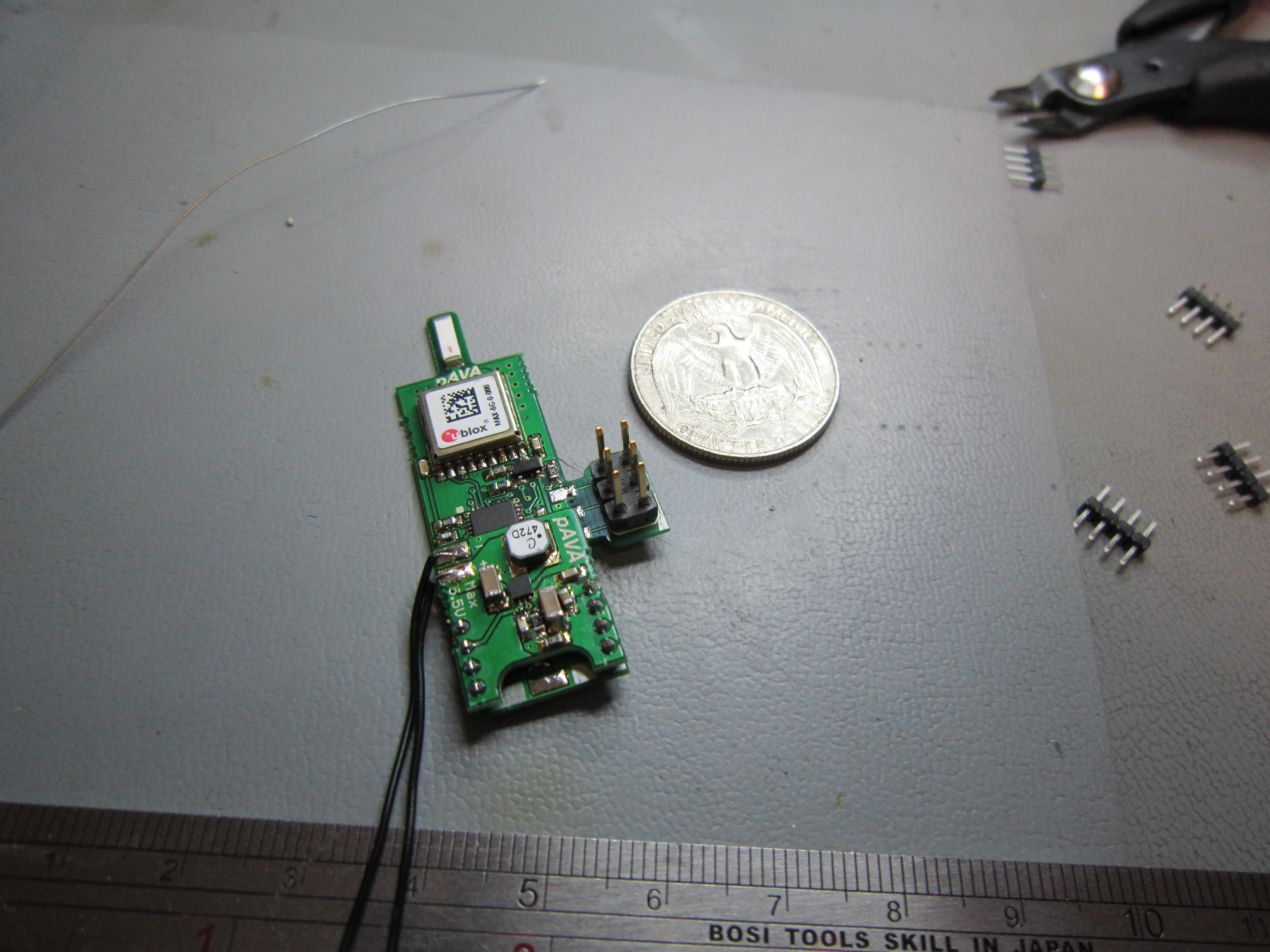
The bane of my life the ICSP programming header, after an off the cuff comment from Mark Jessop about snapping it off I came up with a design for a snap off ICSP header allowing easy programming with a standard header and then the ability to snap it off before launch.
With Leo’s successful launches using solar I wanted to also give the board flexible power options, retaining my tried and tested LTC3526 step up but also having an option for solar + lipo power. Rather than sticking all this on one board I decided to mezzanine the power board onto the tracker board. So you can pick which power source the tracker uses.
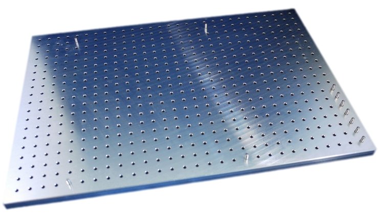
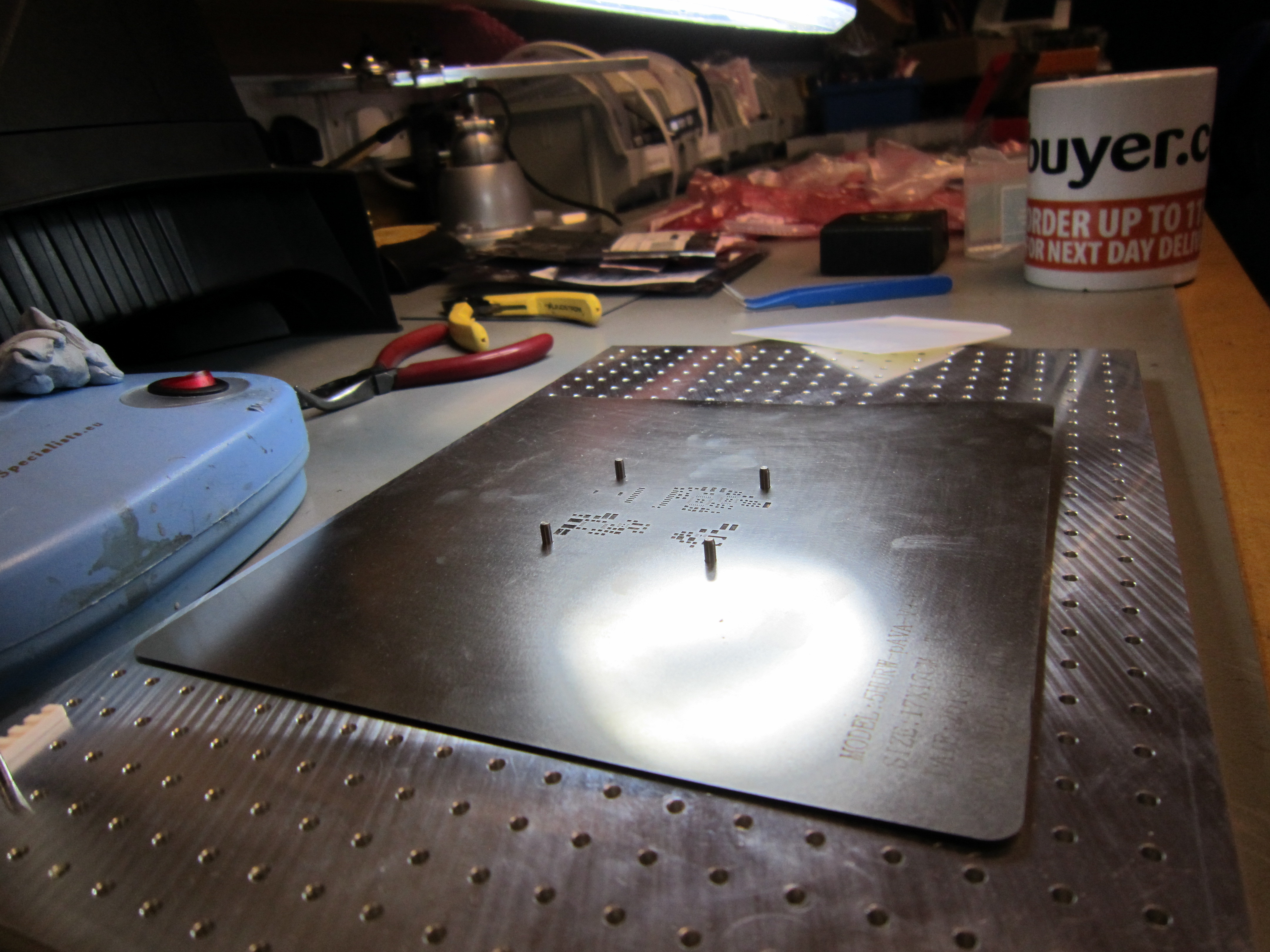
Finally I took the opportunity to try some new (to me) production techniques. Firstly I acquired a Stencil8 clone peg board from Arachnid Labs :
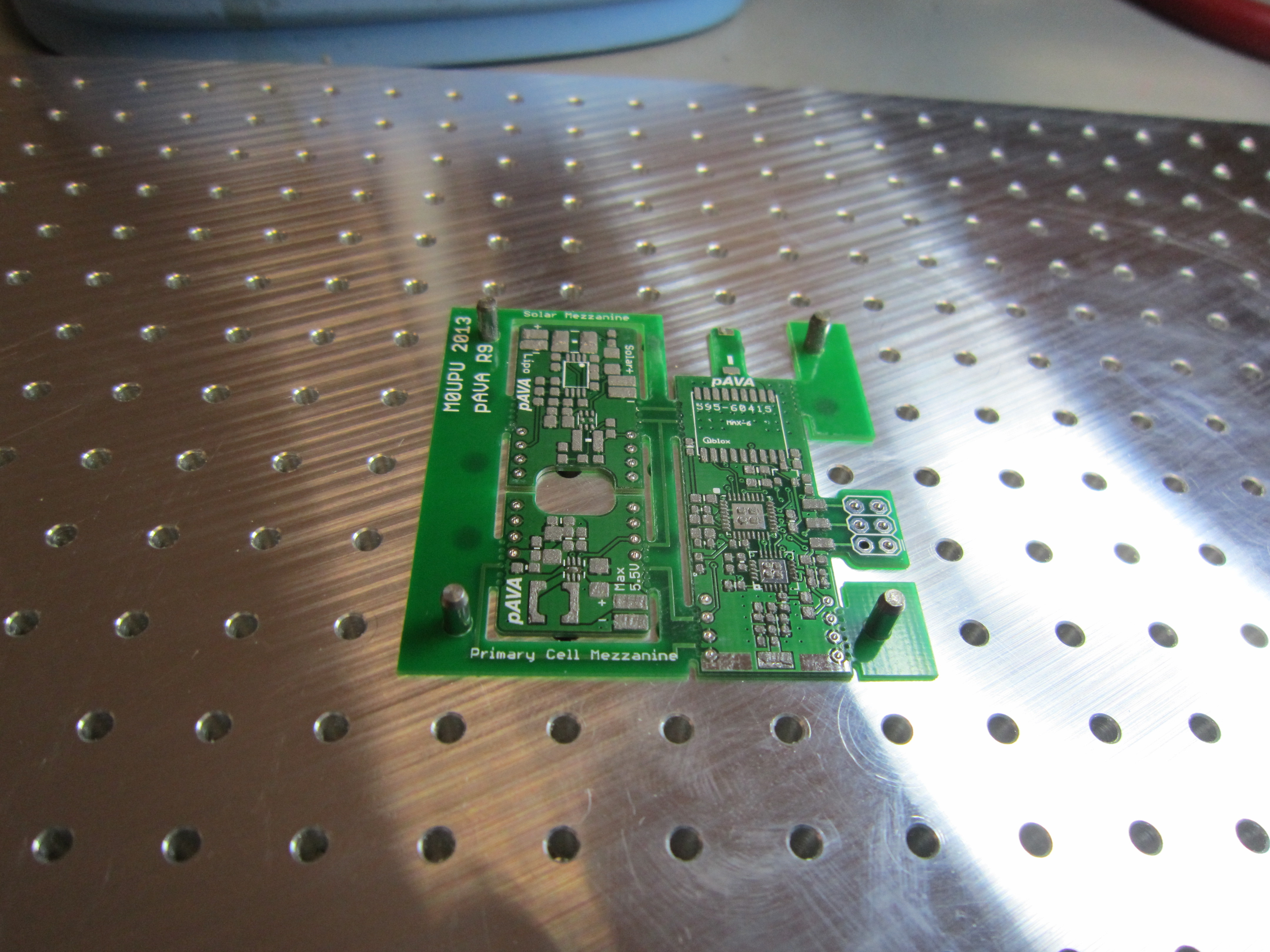
So I didn’t have to get three separate PCB’s made up I did my first “framed” board in Eagle with mouse bites to snap the individual boards out :
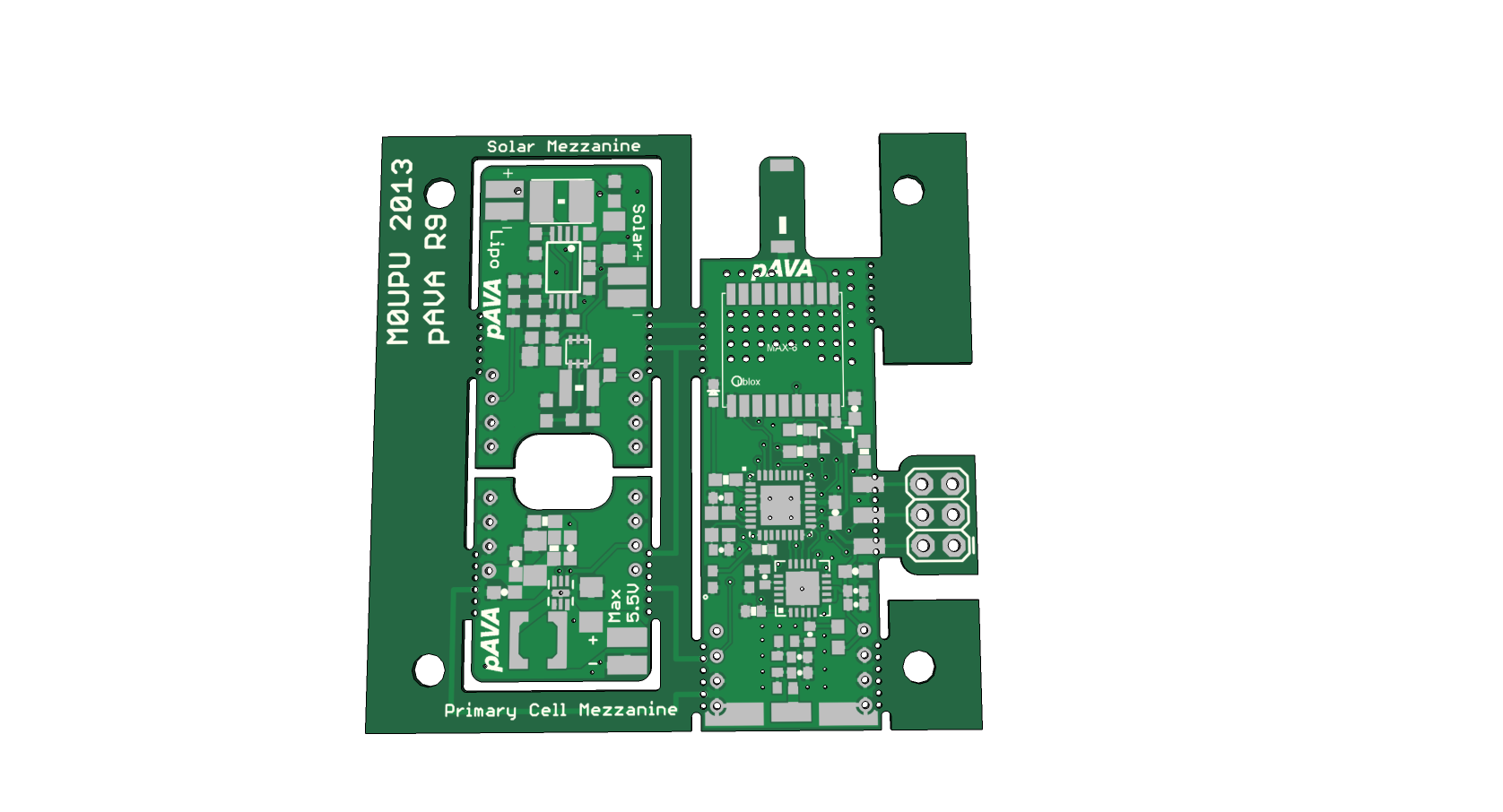
On the right is the tracker board, on the left bottom is the step up and left top is the Lipo + Solar board. Note snap off ICSP header. I ordered these from Hackvana.com along with a stencil which duly arrived :
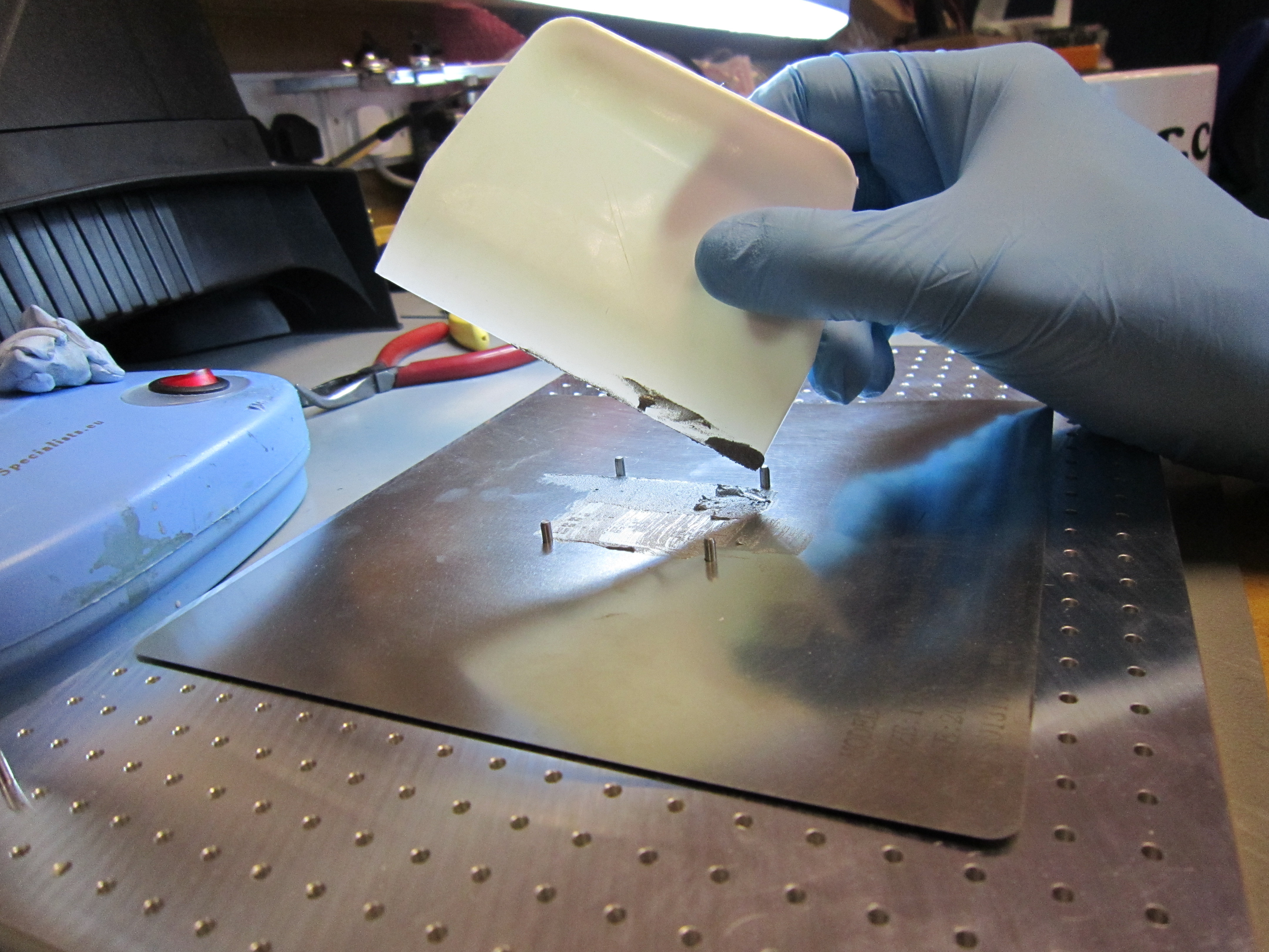

The finished result after spending 7 mins in a T962A Oven and snapped out :
And with the step up power board installed on top.
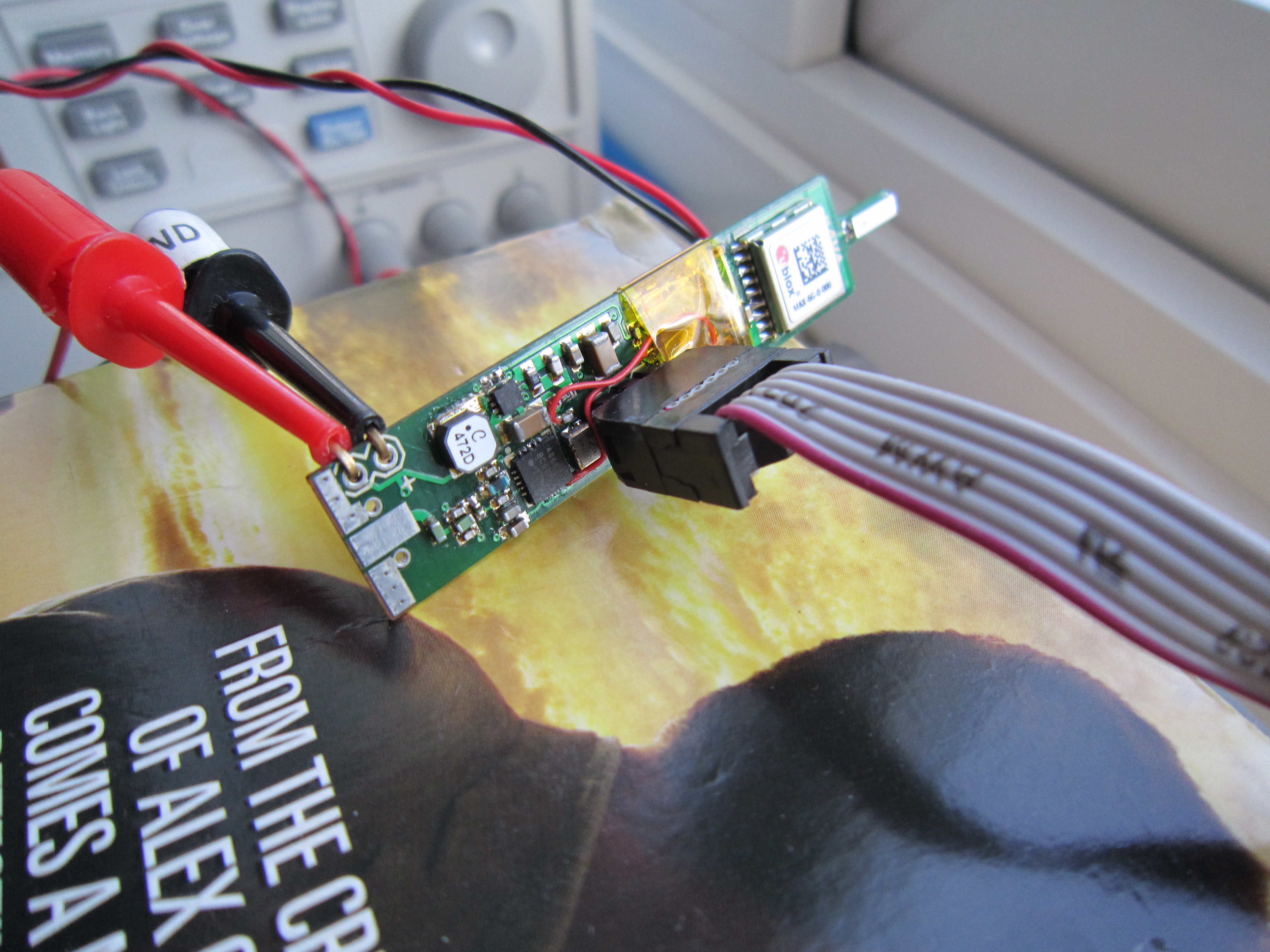
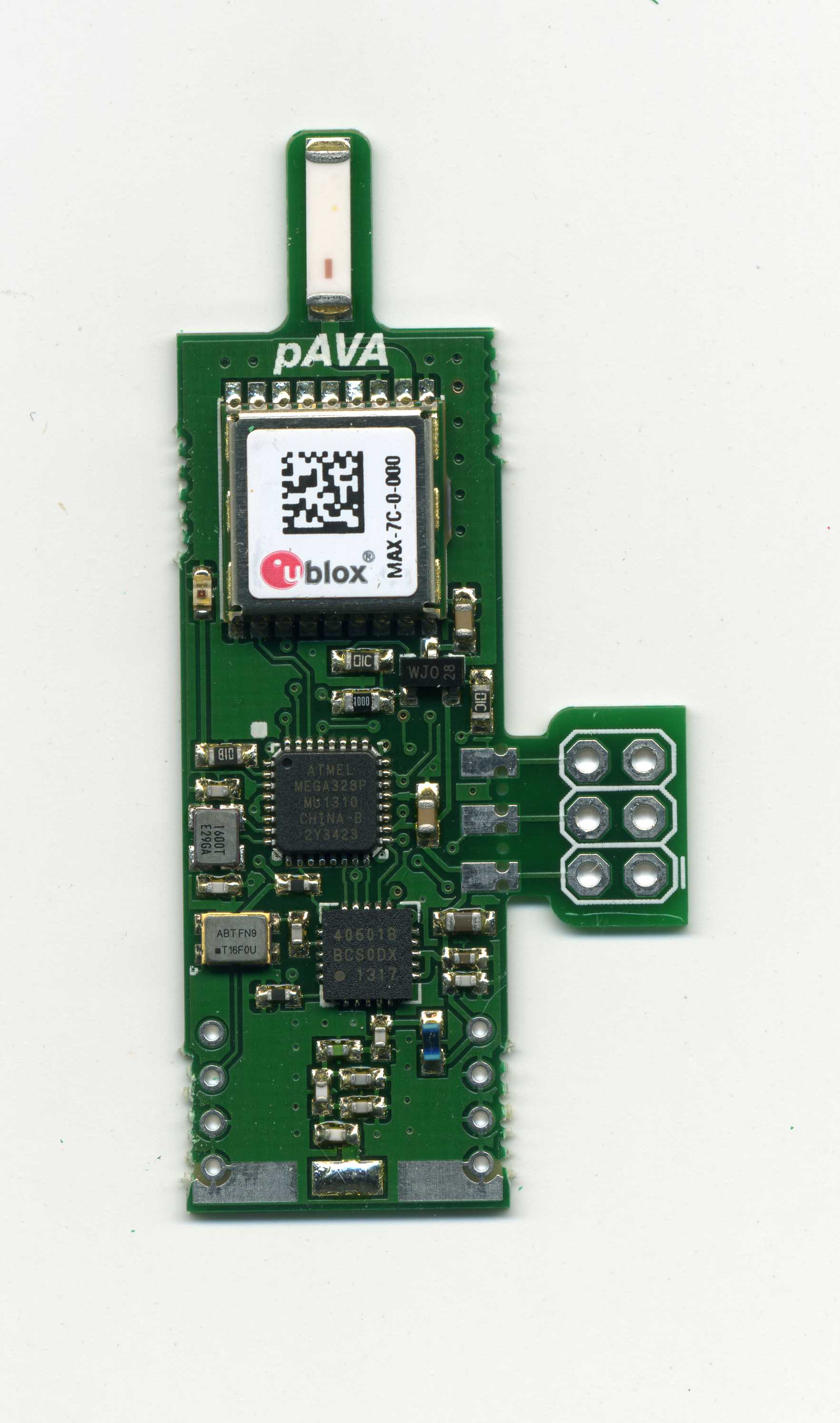
After a few initial false starts (solder had leaked down the snap of ICSP connector and shorted GND and VCC out, also I’d mounted the µC crystal incorrectly) the board was soon transmitting RTTY using the code developed on the R8 board.
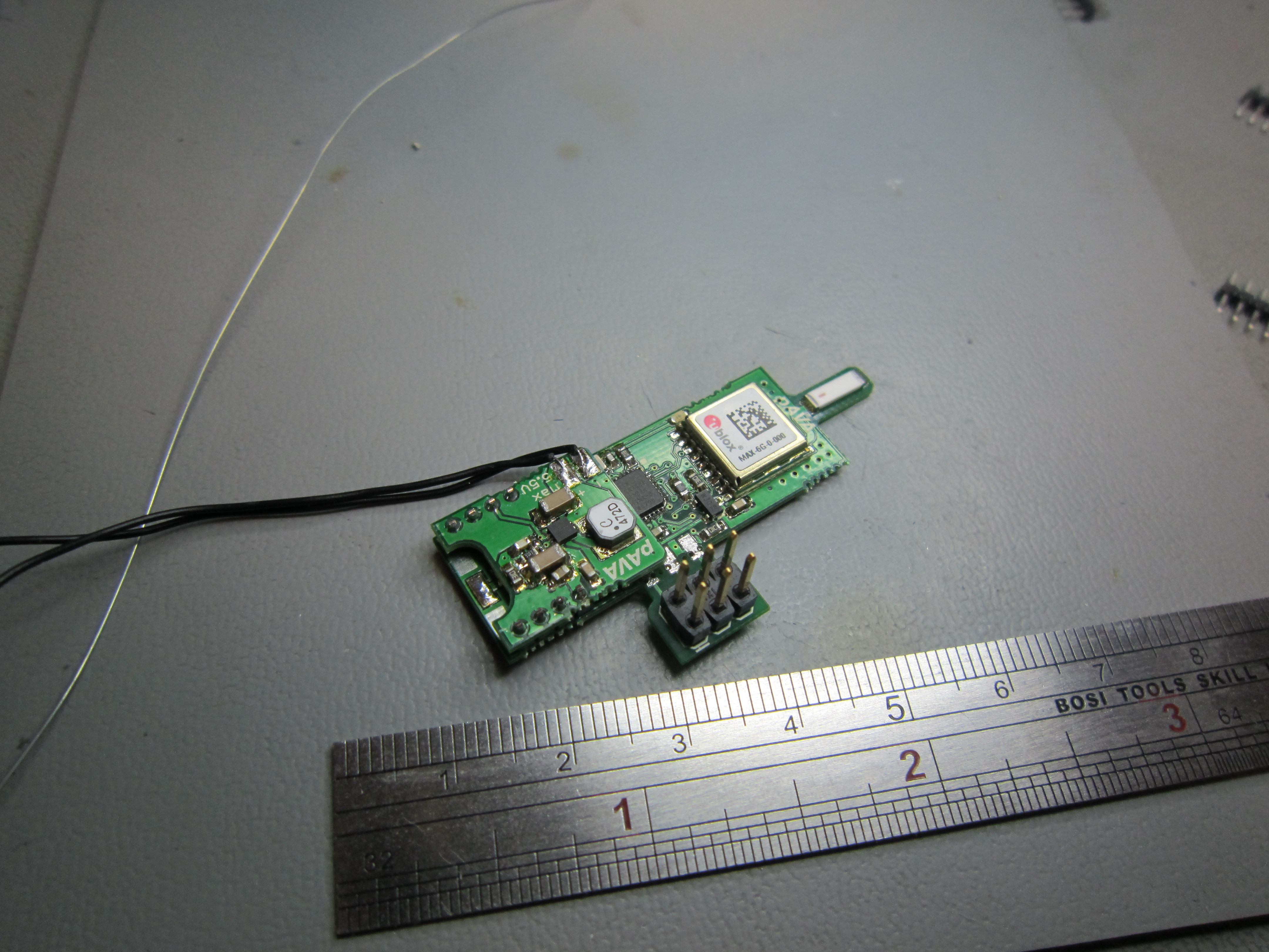
Power consumption via the LTC3526 was quite impressive too. Using the MAX7C and 2Mhz AVR the board was, with the existing power saving code, using 30% less power than the previous board. With a guitar string antenna and an AAA soldered in place I hung the board out in my back garden for a run test.
Weathering out a fairly nasty storm the board transmitted its new DominoEX16 code continuously for 28.5 hours before the battery gave out. This equates to over 70 hours from an AA. This is without any real power saving improvements over the code developed for the R7 board here : http://ava.upuaut.net/?p=437
Quite a big jump from 45 hours!
Hello Upu, that’s looking groovy baby!
If soldering the programming header bugs you, one idea is to use some pogo pins to make a “bed of nails”. And if you always had the programmer sticking out the side like that, you could make a standard jig for programming.
“……. 16.369Mhz crystal would give a minimum step size on the SI4060 of (FCrystal/2^21) = 8.18Hz. The step size for DominoEX16 is 15.675Hz so 2 x step = 16.37Hz which is close enough.”
Errata (correction):
16369000Hz / (2^21) = 7.805347Hz (no: 8.18Hz)
2×7.805 = step: 15.61Hz ~ (standard dominoEX16 Baud=15.625Hz (no: 15.675Hz)
Ooops wrong button on my calc you are correct!
I’ve never done any hobbyist surface mount boards before – just the normal two-sided through hole kind.
Using a stencil and solder paste is neat! How do you place the components and get them into the oven without everything shifting? The only times I’ve dealt with surface mount components, I had to tack-solder one pin to keep the whole business from flying away when I just breathed too hard.
Hi
Is it possible to buy the pAVA R8 ?
My best reg 73 SM2UHF
Lars
Evening Lars,
Sorry it was only ever a pet project, they are quite fiddly to make. I do however sell the Habduino and Pi In The Sky which are obviously much larger but effectively the same.
Cheers,
Anthony M0UPU
Greetings Anthony,
First off, I want to say that I’m thoroughly impressed by your work on this sat board. Very small and very capable. I was wondering if you were planning on releasing the schematic and code used in the build? I’ve been hard at work learning surface mount devices through trial and error and I like the use of the “mouse bites” to be able to build and test on the bench without fully assembling the complete package and then reduce the size and weight before deployment. Your code would also be beneficial to learn more about scaling the uC down to 2Mhz and how to go about talking to the radio transceiver chip.
I’ve come back to this page so many times for inspiration. I appreciate what you’ve done and would be greatful to learn more from you.
Thank you,
Christian
Hi Christian,
Thanks for your kind comments. In the end I didn’t release the hardware design to this because it was just a prototype to see if I could make something like this work. The code is here https://github.com/Upuaut/uAVA/tree/master/pava9_thor
Running the µC @ 2Mhz is fairly trivial, you just use a 16Mhz crystal and set the DIV/8 fuse. This gets it down so you can use 1.8V.
Cheers,
Anthony