
This is an article on making a network attached Stratum 1 NTP Server using a Raspberry Pi+ Model 2 or 3 and the Uputronics Raspberry Pi+ GPS Expansion Board. If you need a standalone ready to go solution or need more performance please consider the LeoNTP Networked Time server unit which is available here.
Due to significant changes to Raspbian we have decided to retire the old guide here https://ava.upuaut.net/?p=726 and redo it.This guide assumes Raspbian Stretch Lite November 2018 released 2018-11-13. No other version or distribution is supported.
This solution will not give you a standalone off grid NTP server. NTP isn’t designed to work off grid using just the NMEA derived time and PPS to discipline it. You need an external server and then use PPS to discipline it.
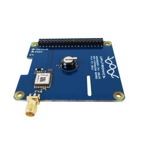
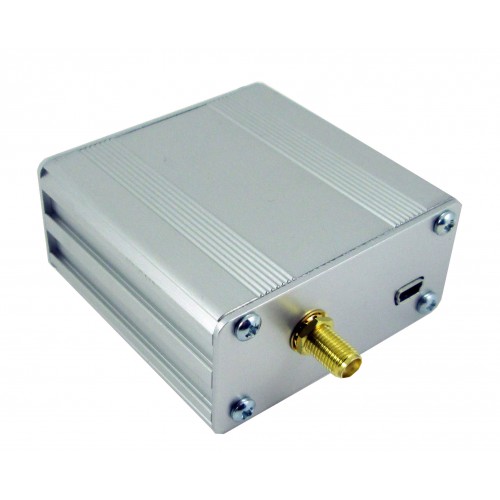
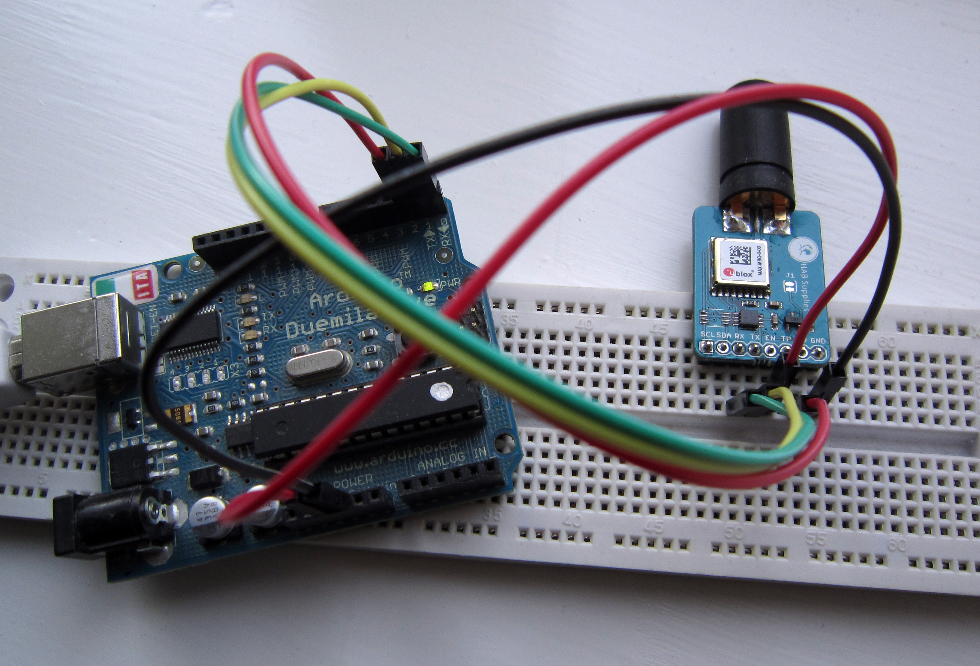
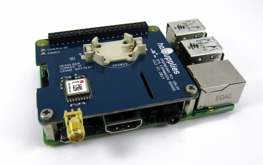
Uputronics Raspberry Pi+ GPS Expansion Board
Ideally rather than supplying a premade image I would have a set of concise instructions on making your own install from scratch so you could use the latest versions of the software. With assistance from David Taylor who did lots of background work on this here I present the following instructions on making a cheap PPS disciplined NTP Time server using one of the Raspberry Pi+ GPS boards sold on Uputronics.
The guide assumes you have a cursory knowledge of Linux, enough to install Raspbian and login should do.
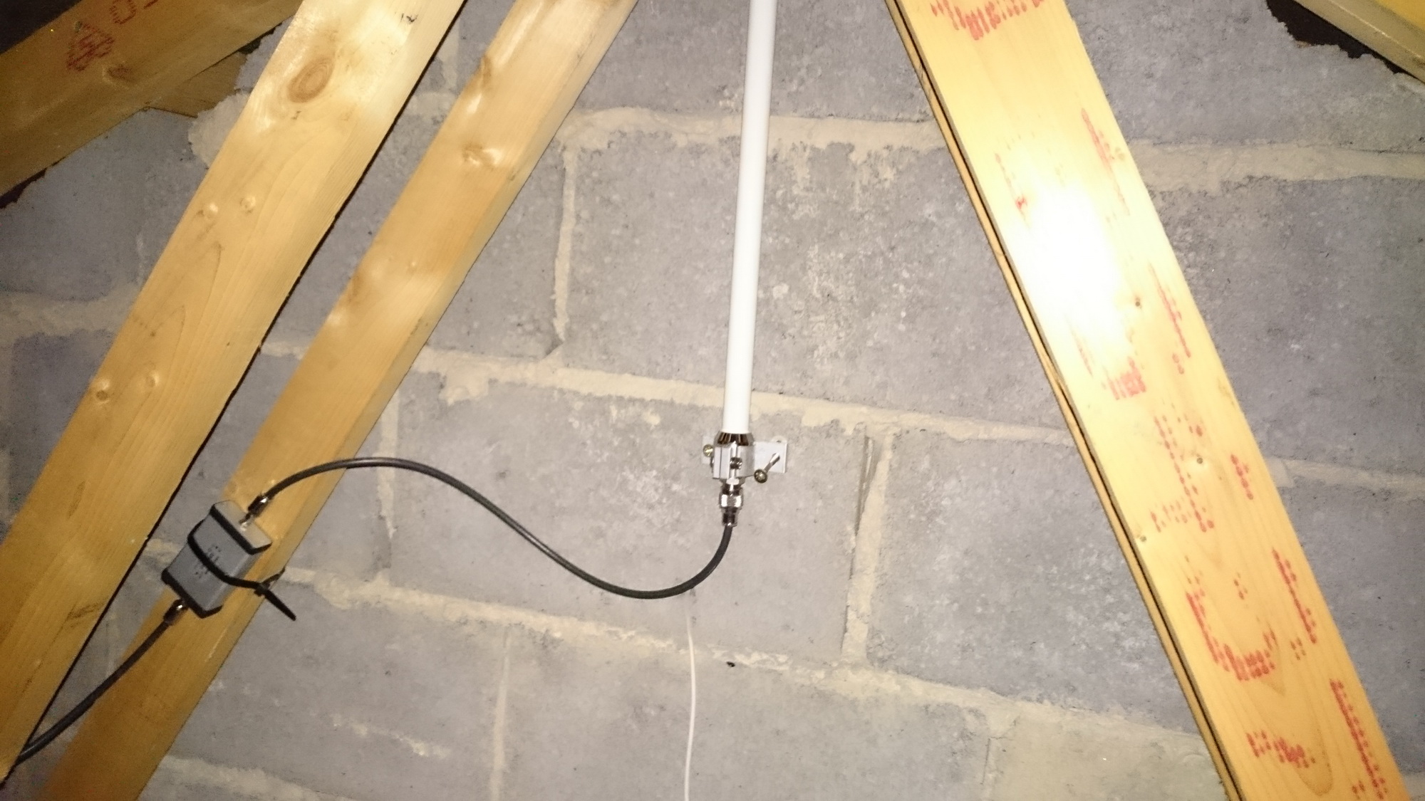
You will need a Raspberry Pi 2 or 3 B+, the Uputronics Raspberry Pi+ GPS Expansion Board and a suitable GPS antenna.
This guide is assuming you’re using Raspbian Stretch Lite November 2018 released 2018-11-13 image. Download and write this to an SD card (See http://www.raspberrypi.org/documentation/installation/installing-images/README.md). Other distributions may work but these instructions are known to work with Raspbian Stretch Lite.
Attach the Uputronics Raspberry Pi+ GPS Expansion Board to the Pi, insert the SD card, connect the antenna and network cable and boot the Pi up. Either connect locally or via SSH to the Pi (If you can’t SSH in and don’t have a monitor see this https://www.raspberrypi.org/documentation/configuration/wireless/headless.md)
Follow the instructions carefully if you miss steps things won’t work.
Text in italics is what you type.
Text in red indicates editing inside a file.
Prerequisite Settings
sudo raspi-config
5 Interfacing Options
P2 SSH -> Would you like the SSH server to be enabled – YES (Recommended)
P6 Serial -> Login Shell (no) Hardware (yes) (Optional)
Quit but no need to reboot at this point.
sudo nano /boot/config.txt
Add at the bottom :
dtoverlay=pps-gpio,gpiopin=18
Save and Quit Nano.
sudo apt-get update
sudo systemctl disable hciuart
sudo systemctl mask [email protected]
sudo apt-get install pps-tools ntp dnsutils
sudo reboot
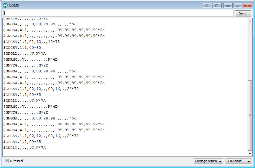
Verifying PPS Is Working
Ensure the GPS has a lock and the Green PPS LED on the Uputronics Pi+ GPS Expansion Board is blinking once a second.
dmesg | grep pps
Output should be similar to :
[ 2.443494] pps_core: LinuxPPS API ver. 1 registered
[ 2.446699] pps_core: Software ver. 5.3.6 - Copyright 2005-2007 Rodolfo Giometti <[email protected]>
[ 2.471796] pps pps0: new PPS source pps.-1
[ 2.471886] pps pps0: Registered IRQ 498 as PPS source
[ 6.965166] pps_ldisc: PPS line discipline registered
[ 6.966569] pps pps1: new PPS source ttyAMA0
[ 6.966664] pps pps1: source "/dev/ttyAMA0" added
sudo ppstest /dev/pps0
Output should be similar to:
 trying PPS source "/dev/pps0"
 found PPS source "/dev/pps0"
 ok, found 1 source(s), now start fetching data...
 source 0 - assert 1418933982.998042450, sequence: 970 - clear  0.000000000, sequence: 0
 source 0 - assert 1418933983.998045441, sequence: 971 - clear  0.000000000, sequence: 0
(Press CTRL+C to quit). This indicates the PPS Module is loaded (top example) and is working (bottom).
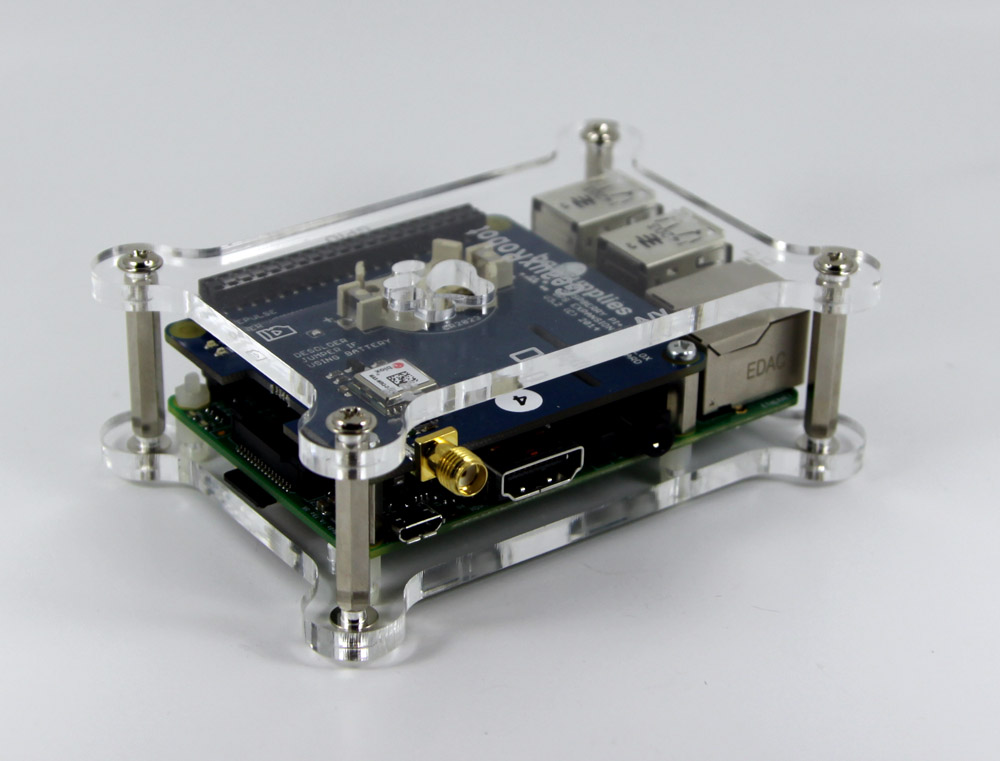
GPS board mounted in Geaux Robot Dog Bone Case for Raspberry Pi B+ also available from Uputronics
Enabling PPS/ATOM Support in NTPD
The supplied version of NTPD on the Raspberry Pi now supports PPS so there is no need to roll your own NTP.
You need to pick a few local NTP servers to use. The easiest way to do this is pick your region:
https://support.ntp.org/bin/view/Servers/NTPPoolServers
Select your region then you get a list of the country servers. E.g for the UK its uk.pool.ntp.org.
Type:
dig uk.pool.ntp.org
You will get four IP’s back:
; <<>> DiG 9.10.3-P4-Raspbian <<>> +answer uk.pool.ntp.org
;; global options: +cmd
;; Got answer:
;; ->>HEADER<<- opcode: QUERY, status: NOERROR, id: 51647
;; flags: qr rd ra; QUERY: 1, ANSWER: 4, AUTHORITY: 0, ADDITIONAL: 1

;; OPT PSEUDOSECTION:
; EDNS: version: 0, flags:; udp: 4000
;; QUESTION SECTION:
;uk.pool.ntp.org. IN A

;; ANSWER SECTION:
uk.pool.ntp.org. 24 IN A 193.150.34.2
uk.pool.ntp.org. 24 IN A 176.58.109.199
uk.pool.ntp.org. 24 IN A 195.195.221.100
uk.pool.ntp.org. 24 IN A 185.53.93.157
sudo nano /etc/ntp.conf
Add
server 127.127.22.0 minpoll 4 maxpoll 4
fudge 127.127.22.0 flag3 1 refid PPS
tos mindis 0.2
Comment out all the pool lines:
#pool 0.debian.pool.ntp.org iburst
#pool 1.debian.pool.ntp.org iburst
#pool 2.debian.pool.ntp.org iburst
#pool 3.debian.pool.ntp.org iburst
Add the four servers from the dig command with the top one saying prefer on it:
server 193.150.34.2 iburst prefer
server 176.58.109.199 iburst
server 195.195.221.100 iburst
server 185.53.193.157 iburst
You may also want to add your local lan to so you can query the NTP Server by adding:
restrict 192.168.1.0 mask 255.255.255.0
Note You MUST add a preferred server or PPS doesn’t work. Its worth at this point seeing if you’re ISP has its own NTP server you can use and adding that.
Save and close nano.
sudo service ntp restart
After a few minutes run
ntpq –p
if you get oPPS(0) this indicates source selected, Pulse Per Second (PPS) used and everything is working.
If you aren’t seeing the settings its possible the NTP server is picking up the NTP information via DHCP which is over riding your settings above. Do this :
rm /etc/dhcp/dhclient-exit-hooks.d/ntp
rm /var/lib/ntp/ntp.conf.dhcp
At this point you have a NTP server which will use an external time source and use your local PPS to discipline it.
Setting Stationary Mode
David Taylor’s website here http://satsignal.eu/ntp/Raspberry-Pi-NTP.html goes into much further detail about the process above and covers graphing, remote access monitoring etc and I highly recommend you read it.
Hope this helps, let me know how you get on with these instructions and I’ll try keep them up to date.
Thanks to:
David Taylor
Dave Akerman
sout + others on #ntp irc.freenode.org


Grab this small program code here : https://pastebin.com/YTc9Nd3D
Compile + link:
May take a few goes to set it.
pi@hypatia:~ $ sudo ./gpsControl -s -d /dev/ttyAMA0
Set GPS for stationary mode
Configuring device /dev/ttyAMA0
>>>>>>>>>>>>>>>>>>>>> SENDING >>>>>>>>>>>>>>>
>>>>>>>>>>>>>>>>>>>>> SENDING >>>>>>>>>>>>>>>
GPS mode set OK
Static IP + Hostname
If you want to fix your LAN IP you do it by amending /etc/dhcpcd.conf adding the following lines:
interface eth0
static ip_address=192.168.1.7/24
static routers=192.168.1.254
static domain_name_servers=8.8.8.8 8.8.4.4
Amend your hostname by editing /etc/hostname and then adding this to /etc/hosts as well. I.e if you call your machine ‘eleanor’ add this after localhost in /etc/hosts:
127.0.0.1 localhost eleanor
Further Reading