
We no longer make these boards sorry !
Thanks for all your interest over the years but unfortunately we are no longer making these boards. All the Eagle plans are available and BOM’s below so you can make your own.
This is what you got :

They were supplied assembled with headers, RJ45 connector, LCD brightness pot, all capacitors, resistors and transistors soldered up. You don’t get the LCD, switches, LED’s or a case of course! The PCB is designed to fit into a Hammond 1598BSGYPB enclosure (Farnell 1426554). Personally I don’t use switches but these are suitable : Multicomp Momentary PTM
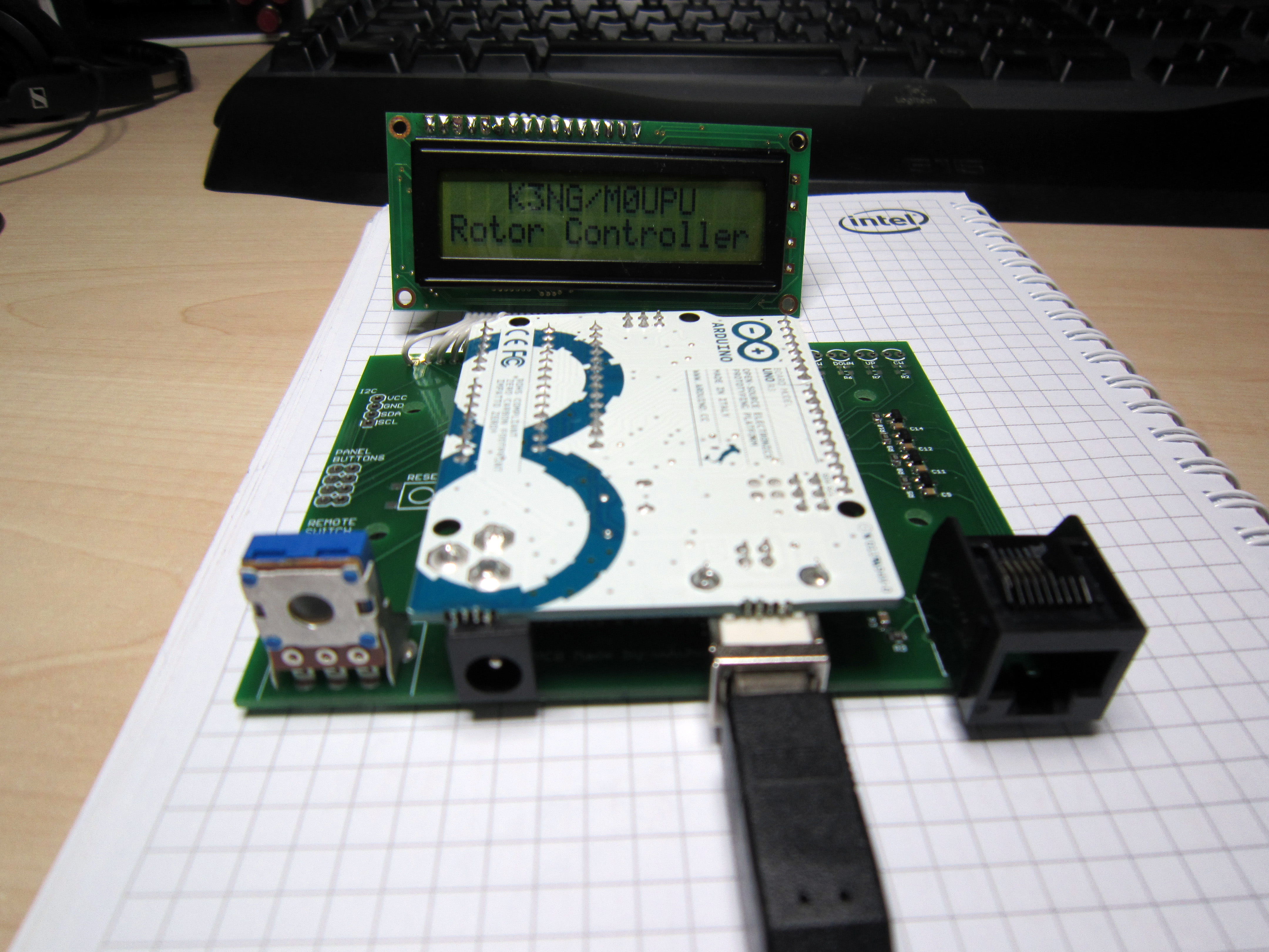
Here it is with an Uno installed :
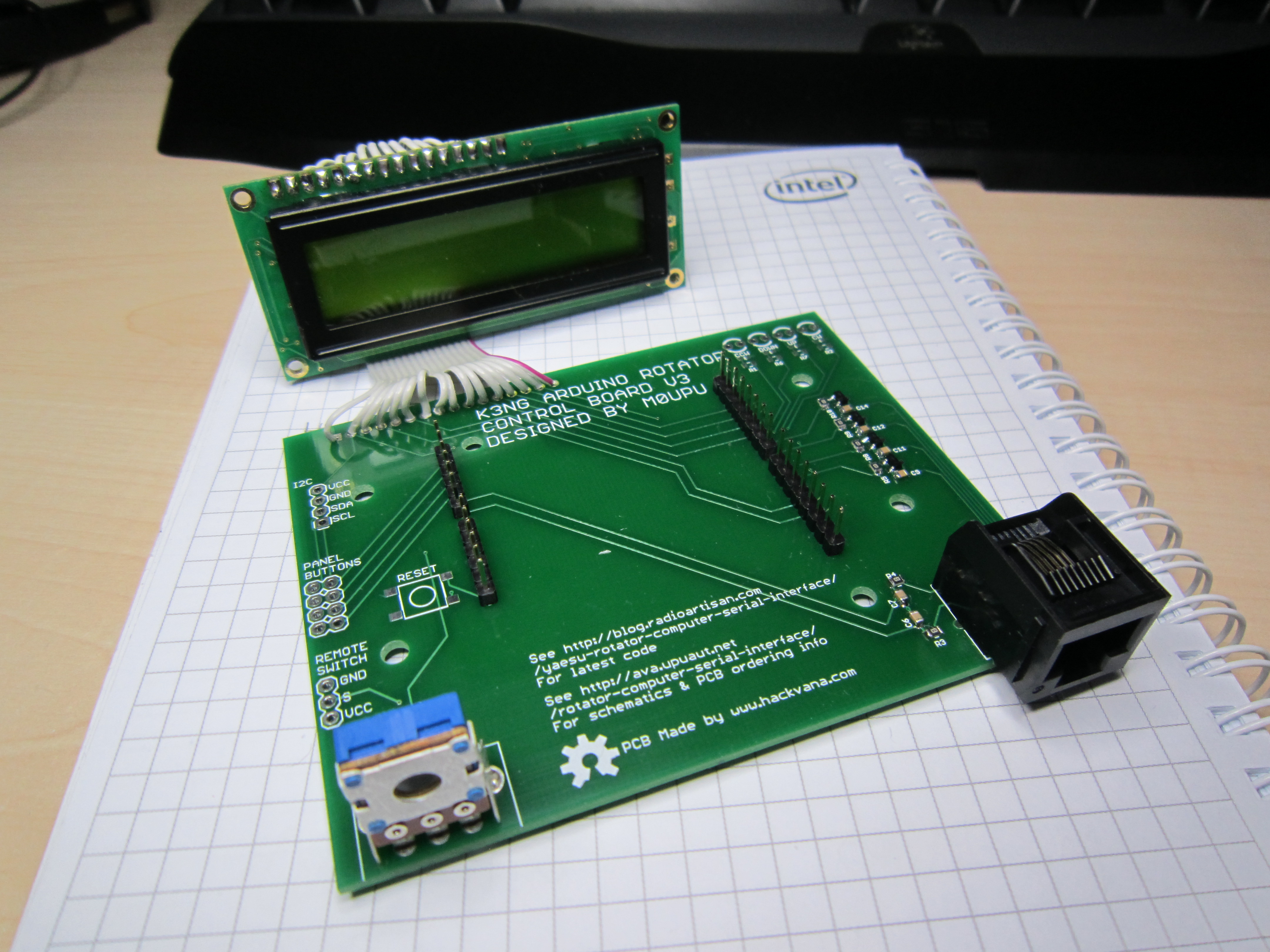
And without :
Update 29/05/2017 :
We are no longer making this board. It was the last board we made by hand and we no longer have the resources to do this. Unfortunately its not viable at the price to get this board made externally therefore we are discontinuing it.
Update 05/05/2013 :
I’ve sold out of the first two batches of these rotator boards so I’ve placed an order for some new ones which should be delivered before the end of May. We took the opportunity to add a few improvements to the PCB. Its still based round the concept of plugging an Arduino Uno or Duemilanove in upside down as per the post below. Additionally we added the following improvements :
1/ LCD back light is linked to a PWM port so you can adjust the LCD back light brightness via code.
2/ Reset switch added.
3/ Added a remote power switch port (I use this to power a relay to turn the controller on see http://ava.upuaut.net/?p=461
4/ Broke out the I2C Ports
5/ Added LED indicators for the axis activations.
6/ Redesigned the board to accommodate changes.
As before I plan to offer this PCB with the headers (RJ45 for rotator connection, Arduino headers and back light dimming resistor) and the switching circuits pre-assembled for about £25 including delivery (will confirm in the next few weeks).
You will need to supply reset switch/LED/LCD if you require these. Personally I use https://www.sparkfun.com/products/709 for the LCD.
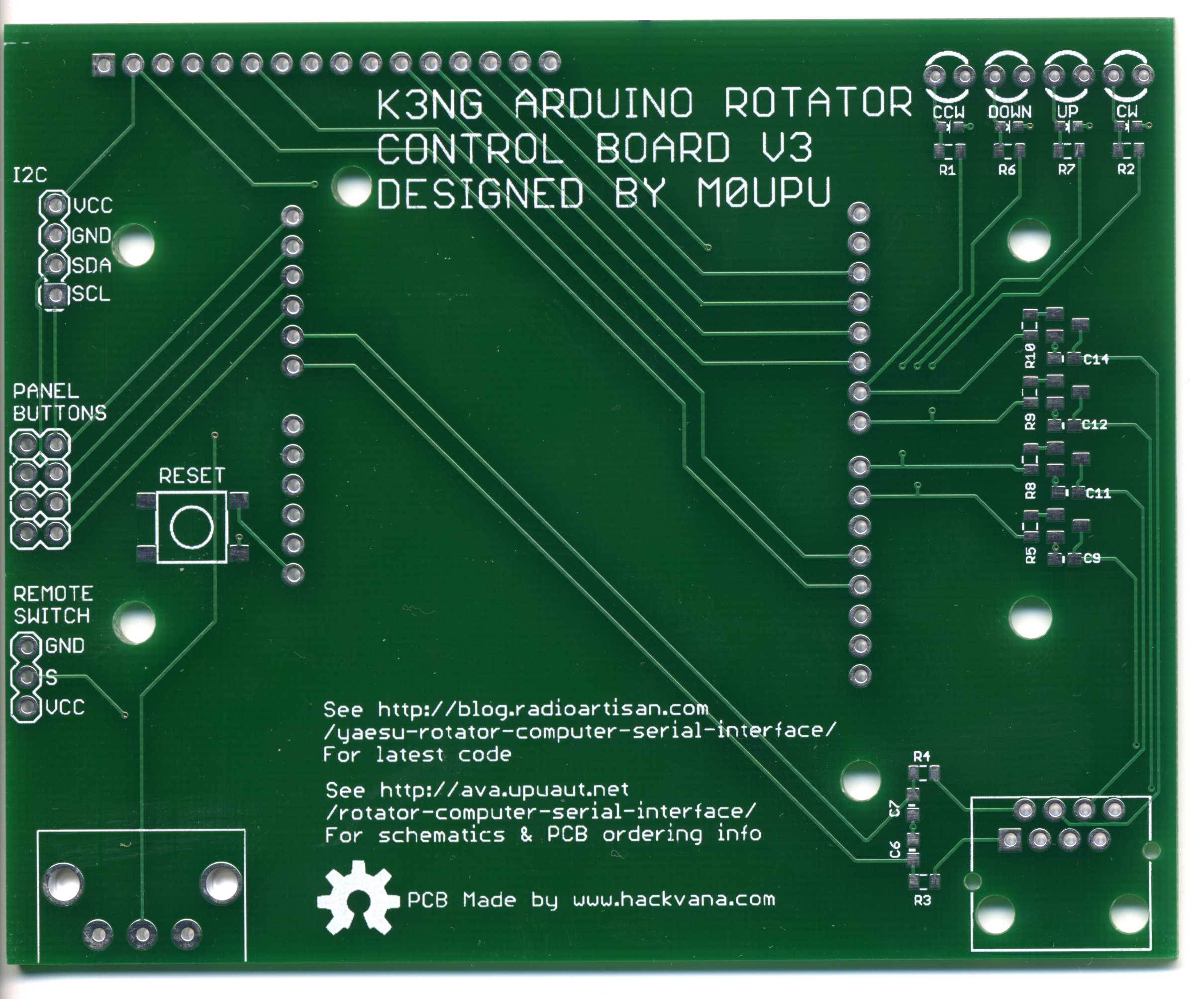
This design has been released as open source the schematic is available for download here : K3NG Rotator Interface V3, the Cadsoft Eagle files here : K3NG Rotator Interface V3. Using the schematic and this image :
You should be able to wire a cable to match your particular rotator controller.
Original Article :
Given my ideal location for tracking on top of a hill I decided last year to beef up the Watson Collinear antenna I was using to a yagi. The only issue with this is the yagi antenna is directional and needs to be pointed at the target. To facilitate this I purchased a Yaesu G-5500 Elevation-Azimuth Rotator unit. This comes with a great controller that has a port on the back to plug in the optional GS-232A controller.
The only downside is the controller is a few hundred quid which given it can be emulated with an Arduino seemed a little bit excessive. Having spent a while searching round the web I came across K3NG’s Arduino Rotator Serial Interface which was by far and away the most complete code I’ve seen.
These days making PCB’s is so cheap thanks to Mitch at Hackvana I decided to make a board for the rotator controller hardware. Initially I was going to make a custom Arduino board with AVR on it etc but then I decided to make it easy and just put a header on there so you could plug an Arduino Uno/Duemilanove on there. This instantly gives you power, the serial interface and is replaceable quite easily.

For the other components I used surface mount 0805 components and transistors. Connection to the rotator was via a CAT5 socket. The large pot on the left is to adjust the screen brightness. The header at the back is to connect an LCD too and there are 4 headers for physical up/down/left/right switches on there.
The Arduino goes in upside down :

Then the LCD plugs in :

Finally it was designed to go in a Hammond enclosure :

Add a 3D printed front bezel :

And voila a nice tidy interface for the controller that costs a damn sight less than the proper Yaesu thing. Now use K3NG’s wonderful code at http://radioartisan.wordpress.com/yaesu-rotator-computer-serial-interface/ to get it up and working.
I’ve released this board as Open Hardware so you are free to use it as you see fit. The Eagle CAD files are here : K3NG Rotator Interface V2
Bill of Materials for the board as follows :
Resistors : all 0805 1K Farnell 9332383
Capacitors : all 0805 0.1µF Farnell 1759143
Transistors : all MMBT2222A Farnell 9846700
RJ45 Jack : TE CONNECTIVITY 3-5338556-1 Farnell 2059819
Pot : TE CONNECTIVITY / CITEC 5350500107 Farnell 1174451
Header : Just buy strips of 1 row 2.54mm pitch header i.e Multicomp MC34743 Farnell 1593425
Case : Hammond 1598BSGYPBK Farnell 1426554
Just a quick warning I did originally intend to have the ICSP header broken out so you can program it via this but I didn’t have my spatial awareness hat on when I made the board and the lines are inverted so as it stands the ICSP break out isn’t usable (unless you plug it in from the rear of the board). This won’t affect you programming the Arduino as normal via the USB.
hi every one maybe some one can help because im pulling my hair out the box is all up and running i have got test buttons that i have put on and thy seem to work fine controlling my yaesu 5500 controler az and el

are fine .. BUT THE ONLY THING IS I CANNOT CONECT TO HRD IM THINKING IT COULD BE THE CODE THAT I HAVE NOT SET UP RIGHT . could some one help me
PLEAS PLEAS PLEAS
Hey Jamie,
Sorry you’re having issues with this, I only do the hardware for coding you’re probably best posting on the Radio Artisan mailing list. Include diagrams of how you have it wired etc.
Jamie
I had the very same problem with HRD. I finally downloaded the
PST_Rotator software and code for my Adrino UNO. I backup up all of my modifications to a seperate folder just in case. I’ve been able to use the KN3G verzion to simulate rotator functions with a meter and LED’s before connecting to my Alliance U-100 Rotator. I’ve stopped there because I just don’t get how the connections work or how they are correctly wired? I have a functional U-100 Rotator and control box. I’ve wired it up and tested it and its 100%. But I had another working box i stripped down and wired up per the schematic and I can’t get it to function….But the PST-Rotator firmware works great.
Alex Watters-KV4PW
Anthony, you seem to skip around the connection interface posts I have looked at and since this is a hardware issue would appreciate clarity I have the Yaesu 450c rotator and understand that the break out from your project is via the RJ45 what you do not make clear is do you parallel tack onto the back of the controller or do you serial off the back of the control unit (control unit meaning Yaesu control unit).
second hard ware question LCD hardware is this a parallel LCD unit or a serial LCD unit? Are there any websites out there that show block diagrams of your hardware the best type of arduino unit to purchase in 2016? 73 G4XCP gail
Hi Gail,
For some background I designed this board for myself to use with my G-5500 Yaesu. I’ve never seen any other rotator nor have I tested it with any other rotator. So I don’t skip the connection questions the usual answer is I just don’t know. However that said all my board is four transistor switches that pull the connected wires down to ground when the Arduino turns them on.
I’m not entirely sure what you mean by parallel tack or serial tack but the schematics are open source here:
http://ava.upuaut.net/wp-content/uploads/2012/10/K3NG-Rotator-Interface-V3.pdf
The RJ45 connection is a standard wiring http://ava.upuaut.net/wp-content/uploads/2012/10/standardmod.gif
The LCD is a parallel one. Personally I’ve only tested this with the Arduino Duemilanovo.
Cheers,
Anthony M0UPU
thank you for your prompt reply
for anyone reading this that has managed to interface this unit with the Yaesu 450c control unit which does not have a remote port on the back do I connect from the MOUPU RJ45 directly to the left right controls on the Yaesu 450 control unit or is another interface needed. How would you wire this to the control unit would you connect in parallel to the switches? any information much appricated which would help me and also others reading this too
73s
G4XCP
Have you tried the Radio Artisan mailing list ? https://groups.yahoo.com/neo/groups/radioartisan/info
Hello gail,
Just saw your message.The answer is you cannot connect it directly to G450c.If you look at the G450c schematic,the left/Right switches reverse the polarity to Rotator motor.You will need some kind of interface between your controller and rotator.
73
AP2AM
hello
I’d be interested in your Arduino UNO with a rotator control my question is can I use it with my Yaesu G1000DXC and connect the output yaesu ext controller?
could you confirm the price with the UNO?
Hi Bruno,
I’m not sure I don’t have experience with that unit. All the board is a few transistors acting as switches to control “something” on and off. The circuit diagram is open source and in the post so you are welcome to ascertain if it will work for your application. I only sell the board, the Uno you’d have to source from elsewhere like Sparkfun or Adafruit.
Cheers
Are these still in stock? Placed an order a week ago for one, nothing has arrived, tried to mail terry@nevis but it bounced.
Hi Peter,
Yes sorry about the delay we had a run on them and we need to make some more. We should have them out by middle of next week, we’ll confirm via Paypal when they ship.
Cheers,
Anthony
Hi I would like to purchase a board please. Do you still have in stock? Regards Lawrence ZL1LDS
Yep we sure do cheers!
>I’ve released this board as Open Hardware so you are free to use it as >you see fit. The Eagle CAD files are here : K3NG Rotator Interface V2
Version 3 (with back light connections) is hosted here:
http://ava.upuaut.net/wp-content/uploads/2012/10/K3NG-Rotator-Interface-V3.zip
I would recommend you host/archive a stable version of the code that works with V3 to save support problems. The newer versions of the radioartisan are getting too big for an uno, but simpler code is fine. If users could download preset code from you this would make things easier. I can help with this if needed.
Hi Dan,
Good point, I’ve not see the K3NG code for a few years now didn’t realises this was the case. Feel free to link me the code and I’m happy to link it in the article.
Cheers
Does the controller use zdravstvuyte.mozhno with homemade rotary device
have delivery to Russia ?
hi there use your controller .A rotating antennas , used in conjunction with a homemade turning device ?whether it will be will integrate them with the program Orbitron ? for putting satellites ? and whether delivery to Russia is possible ?
We do deliver to Russia. The only rotator I’ve tested it with is a Yaesu G-5500.
I don’t know sorry. If just pulls lines high and low so if thats how your rotator works then yes.Not sure about Orbitron I’ve not used it.
Hi All,
I’ve had mine built for the past weeks but thought it was broken then I took a closer look. I see K3NG on the screen but i have no backlight!
I’m at work and don’t have a meter to the if I’m getting voltage to pin 15 (it’s a regular LCD not I2C)
What can I check in the mean time until I get to a proper workbench?
Hi Frank,
Well firstly check it has a back light on it, some don’t. You should be able to wire VO on the LCD to 3V/5V (check the LCD tolerance) this is normally pin 3 on the LED. Also check the code is bringing PB2 high.
Cheers
Thanks!
It has a backlight, pins 15 and 16 on the LCD. Which of the .h files wiuld let me know if it’s getting turned on? I also noticed it says K3NG on the screen but it’s off-center. I though i saw tgat as ling as i told the code I’m usung m0upu, it would define the lcd rows and columns.
When I configure the file ‘rotator_features_m0upu.h’ for the minimum features, except #define FEATURE_4_BIT_LCD_DISPLAY, the Arduino compiler displays the warnings:
‘Global variables use 1,659 bytes (81%) or dynamic memory, leaving 389 bytes for local variables. Maximum is 2,048 bytes.’
and
‘Low memory available, stability problems May Occur.’
I use Arduino version 1.6.5. Does anyone know if this will indeed be a problem?
Thanks for answering.
Hi Anthony,
is your kit still available?
I want to buy one
What kind of delivery is better for Italy? Economy or Tracked?
73 Paolo iz0dra
Hi Paolo,
Yes still available. Tracked is quicker but more expensive.
Cheers
Hi Rudy,
I don’t have a clue sorry its been (literally) years since I went near the code for this. Possibly best direct this query to the Radioartisan mailing list. My gut feeling is it will be ok.
Cheers
Hi Frank,
I’m not sure about the code any more its been along time since I looked at it. Best direct this query to the Radioartisan mailing list.
Cheers
Hi Anthony,
I ordered your kit.
Please let me know if it’s all ok.
73 de Paolo iz0dra
All ok and will ship today thanks!
Does this support rotator speed control?
Hi there Andy,
The PCB is very simple and supports basically four switches and 2 voltage feedbacks for position so it won’t support anything more complex that said it could be modified to do so. I’m not sure what speed control needs.
Cheers
HI Anthony,
I just placed an order for the assembled board. Which Arduino will fit this board? I had planned on the Mega ADK as they state that is what the code was tested on. Any suggestions?
I will be interfacing it with a G-800DXA 9Same as the G-100DXA)
Thank You
Tom
Hi Tom,
Its designed for the Uno/Duemilanovo boards, I’ve never tried or tested with the Megas so I can’t really assist sorry. Try the Radio Artisan mailing list.
Cheers
Hello may I use an encoder to point the rotator?
Thanks,
Giulio IZ3EAW
Hi Giulio,
The PCB I supply has no facility to connect an encoder. I’m not familiar with the latest K3NG code so it may support encoders. You could hack one on a guess. Best direct this question to the Radio Artisan mailing list.
Cheers
PCB arrived, it’s amazing. Works very well!
Only one more question, where can I find a guide to configure a K3NG code for DCU-1 rotator as for example an Hy Gain? Is it possible to use a K3NG rotator with your PCB?
Thanks for your help and your courtesy,
Giulio IZ3EAW
Hi Giulio,
Thanks for your comment. I’m not familiar with the DCU-1 rotator I would suggest you aim the question at the Radioartisan mailing list here:
https://groups.yahoo.com/neo/groups/radioartisan/info
Cheers
Anthony,
I’d just like to check if you have boards in stock. Interested in building this cool project. Many thanks.
Terry
Hi Terry,
We sold the last one this weekend and they are now discontinued. You are welcome to use the Eagle plans to make your own.
Cheers
Anthony
Hi Anthony,
That’s unfortunate, just my luck But I have the eagle files so I’ll endeavor to get a board made. Can you or anybody here recommend a good pcb fab site where I can get 1 board made ? I’ve used OshPark before, they are great but three boards minimum.
Terry
You can try http://www.hackvana.com but min run is 5 I think , but he’s very cheap. I think one offs are going to be super expensive.
A couple of years ago, I bought a K3NG Rotator PCB from you. I am now putting it together and wonder if you could send me a copy of your software that is ‘tuned’ for your board. I am having difficulty in sorting out the original software and getting all of the parts of the software in the correct place. If not, does anyone else have a copy to suit this board.
Bill
Can you send the eagle files to make my own pcb and adapt to my normal not smd components?
Thans in advance.
EA5ZF Xavi.