
In part 1 of this article I discussed linking the NTX2B to the Arduino and getting a high and low tone out of it. In this article we go one step further and turn this into a transmission of data.
Using the circuit discussed in the previous article upload the following code will transmit a short sentence at 50 baud, 7 bits ASCII 2 stop bits. Also the code adds a CRC checksum at the end of the data string.
The datastring variable is passed to a procedure called rtty_txtstring which takes care of transmitting the data by breaking it down into characters, then it transmits the individual bits of those characters. The key to getting the baud rate correct is the timing. Theoretically 50 baud should be 1/50th of a second = 20000µS however the Arduino delayMicroseconds command can only do a maximum delay of 16383µS. To get round this we do two delays of 10000µS.
300 baud after some playing seemed to be stable around 3370µS delay ( 300 baud should be 1/300s = 3333µS). You can uncomment the relevant lines out as needed.
1 2 3 4 5 6 7 8 9 10 11 12 13 14 15 16 17 18 19 20 21 22 23 24 25 26 27 28 29 30 31 32 33 34 35 36 37 38 39 40 41 42 43 44 45 46 47 48 49 50 51 52 53 54 55 56 57 58 59 60 61 62 63 64 65 66 67 68 69 70 71 72 73 74 75 76 77 78 79 80 81 82 83 84 85 86 87 88 89 90 91 92 93 94 95 96 97 98 99 100 101 102 103 104 105 106 107 108 109 110 111 112 113 114 115 116 117 118 119 120 121 122 123 124 125 126 127 128 129 130 131 132 133 134 135 136 137 138 139 140 141 142 143 144 145 146 147 148 149 150 151 152 153 154 155 156 157 158 159 160 161 162 163 164 165 166 167 168 169 170 171 172 173 174 175 176 177 | /*Demo Code to Drive NTX2B via PWM Written by Anthony Stirk M0UPU RTTY code from Rob Harrison Icarus Project. This example code is in the public domain. */#define RADIOPIN 9#include <string.h>#include <util/crc16.h>char datastring[80];void setup() { pinMode(RADIOPIN,OUTPUT); setPwmFrequency(RADIOPIN, 1);}void loop() { snprintf(datastring,80,"RTTY TEST BEACON RTTY TEST BEACON"); // Puts the text in the datastring unsigned int CHECKSUM = gps_CRC16_checksum(datastring); // Calculates the checksum for this datastring char checksum_str[6]; sprintf(checksum_str, "*%04X\n", CHECKSUM); strcat(datastring,checksum_str); rtty_txstring (datastring);}void rtty_txstring (char * string){/* Simple function to sent a char at a time to ** rtty_txbyte function. ** NB Each char is one byte (8 Bits) */char c;c = *string++;while ( c != '\0') { rtty_txbyte (c); c = *string++; }}void rtty_txbyte (char c){ /* Simple function to sent each bit of a char to ** rtty_txbit function. ** NB The bits are sent Least Significant Bit first ** ** All chars should be preceded with a 0 and ** proceded with a 1. 0 = Start bit; 1 = Stop bit ** */int i;rtty_txbit (0); // Start bit// Send bits for for char LSB firstfor (i=0;i<7;i++) // Change this here 7 or 8 for ASCII-7 / ASCII-8 { if (c & 1) rtty_txbit(1);else rtty_txbit(0);c = c >> 1;}rtty_txbit (1); // Stop bit rtty_txbit (1); // Stop bit}void rtty_txbit (int bit){ if (bit) { // high analogWrite(RADIOPIN,110); } else { // low analogWrite(RADIOPIN,100);}// delayMicroseconds(3370); // 300 baud delayMicroseconds(10000); // For 50 Baud uncomment this and the line below. delayMicroseconds(10150); // You can't do 20150 it just doesn't work as the // largest value that will produce an accurate delay is 16383}uint16_t gps_CRC16_checksum (char *string){ size_t i; uint16_t crc; uint8_t c;crc = 0xFFFF;// Calculate checksum ignoring the first two $s for (i = 2; i < strlen(string); i++) { c = string[i]; crc = _crc_xmodem_update (crc, c); }return crc;}void setPwmFrequency(int pin, int divisor) { byte mode; if(pin == 5 || pin == 6 || pin == 9 || pin == 10) { switch(divisor) { case 1: mode = 0x01; break; case 8: mode = 0x02; break; case 64: mode = 0x03; break; case 256: mode = 0x04; break; case 1024: mode = 0x05; break; default: return; } if(pin == 5 || pin == 6) { TCCR0B = TCCR0B & 0b11111000 | mode; } else { TCCR1B = TCCR1B & 0b11111000 | mode; } } else if(pin == 3 || pin == 11) { switch(divisor) { case 1: mode = 0x01; break; case 8: mode = 0x02; break; case 32: mode = 0x03; break; case 64: mode = 0x04; break; case 128: mode = 0x05; break; case 256: mode = 0x06; break; case 1024: mode = 0x7; break; default: return; } TCCR2B = TCCR2B & 0b11111000 | mode; }} |
Load this up and you should hear the distinctive warble of RTTY coming out of your radio. Route this audio into DL-FLDIGI and you should see the bars in the center of the waterfall like this :
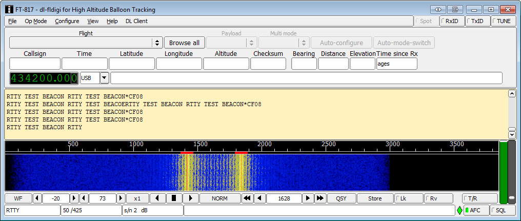
In DL-FLDIGI click Op Mode -> RTTY ->Custom.
Set carrier shift to 425, baud to 50, 7 bits per character, no parity and 2 stop bits. If everything is ok you should see DL-FLDIGI decoding the RTTY.
Part 3 discusses using a similar method transmit DominoEX.
Hi,
A quick follow up on my recent request for advice. I now have a response on Dl fldigi that begins by giving sections of the transmitted NTX2B-FA (using resistors). This is an example: ]11:22,54.9V999tl<hh%rr2$R2%IIR$de$RrdR%I,999tl<hh%rr2$R2dIIII22. The transmitted string was:
$$$$HABham1,181,20:11:22,54.903591,-1.811670,21,1,6*5957.
My apologies, I am aware that I might be pushing things, but have you any advice (still trying to sort out a link with the site you mentioned)?
Regards,
Colin.
Yeah come on IRC we’ll talk you through it :
http://webchat.freenode.net/?channels=highaltitude