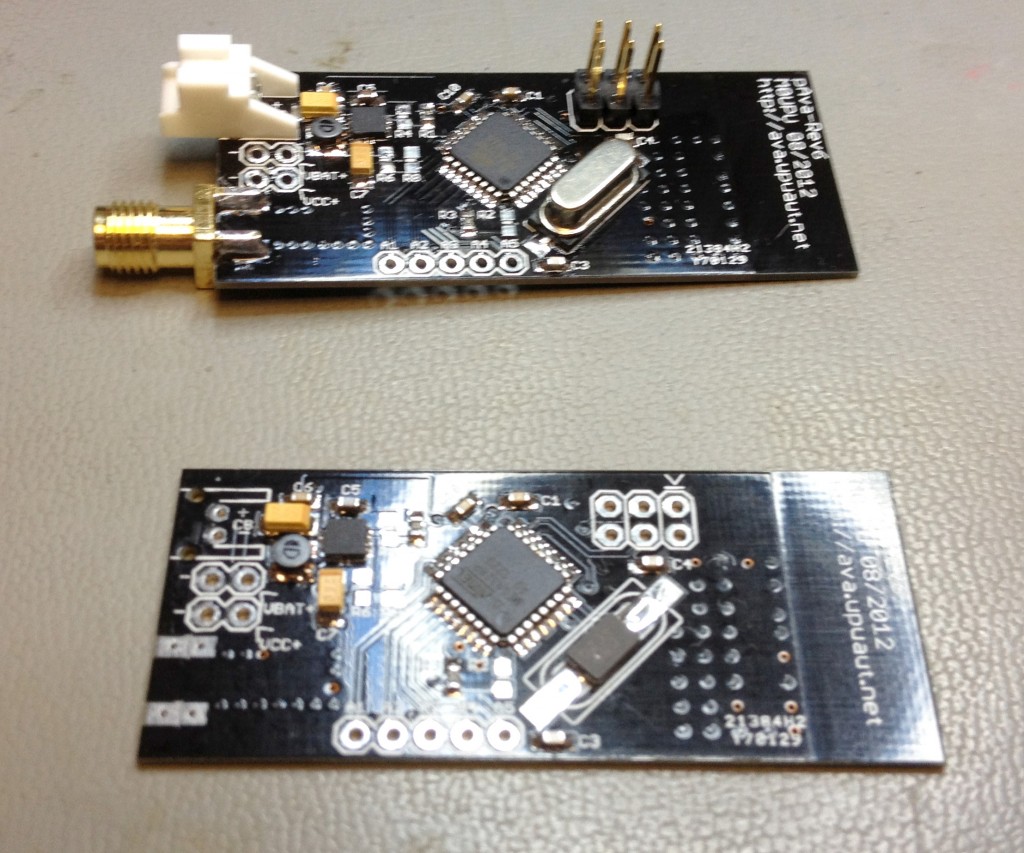
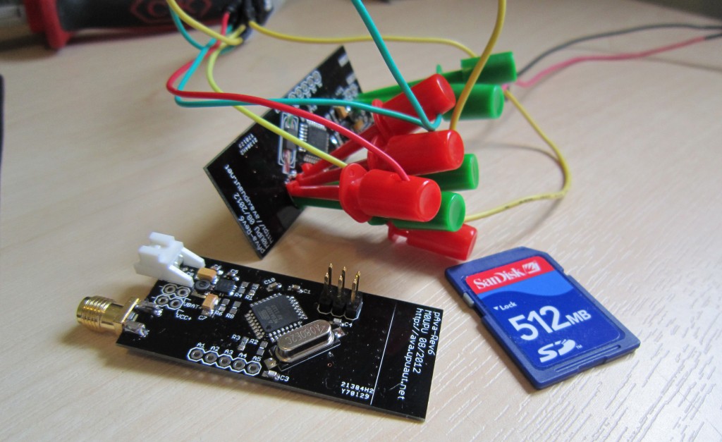
We no longer make these boards sorry !
Thanks for all your interest over the years but unfortunately we are no longer making these boards. All the Eagle plans are available and BOM’s below so you can make your own.
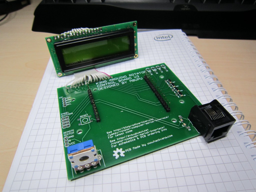
This is what you got :
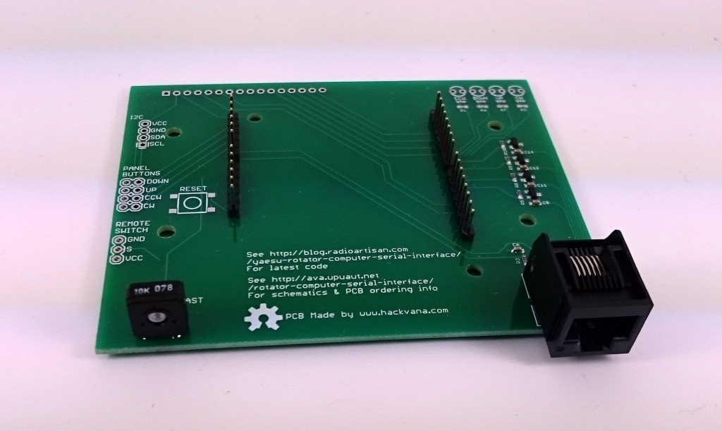
They were supplied assembled with headers, RJ45 connector, LCD brightness pot, all capacitors, resistors and transistors soldered up. You don’t get the LCD, switches, LED’s or a case of course! The PCB is designed to fit into a Hammond 1598BSGYPB enclosure (Farnell 1426554). Personally I don’t use switches but these are suitable : Multicomp Momentary PTM
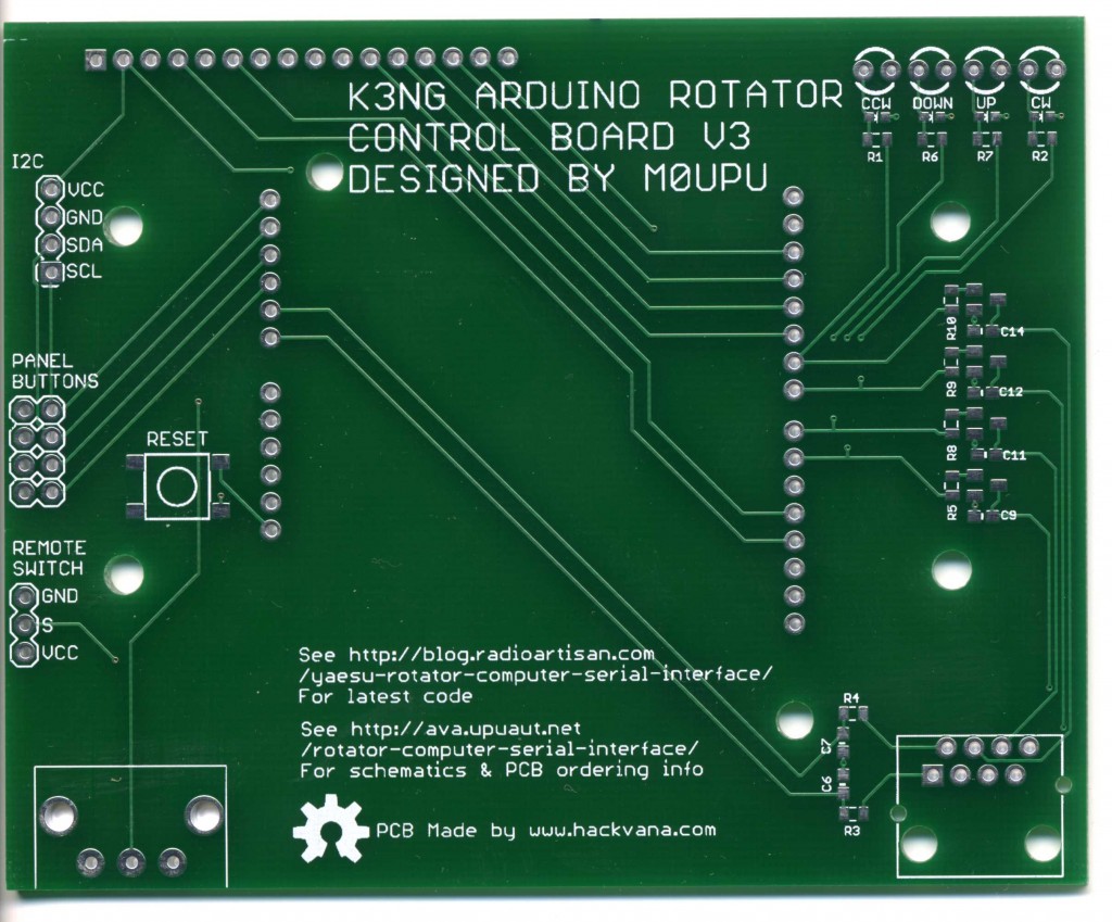
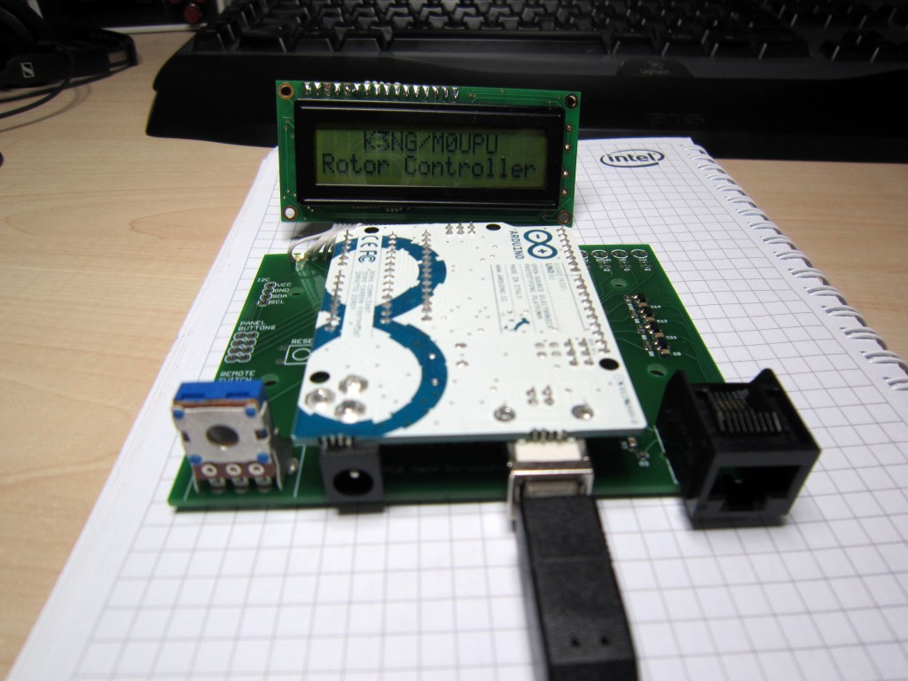
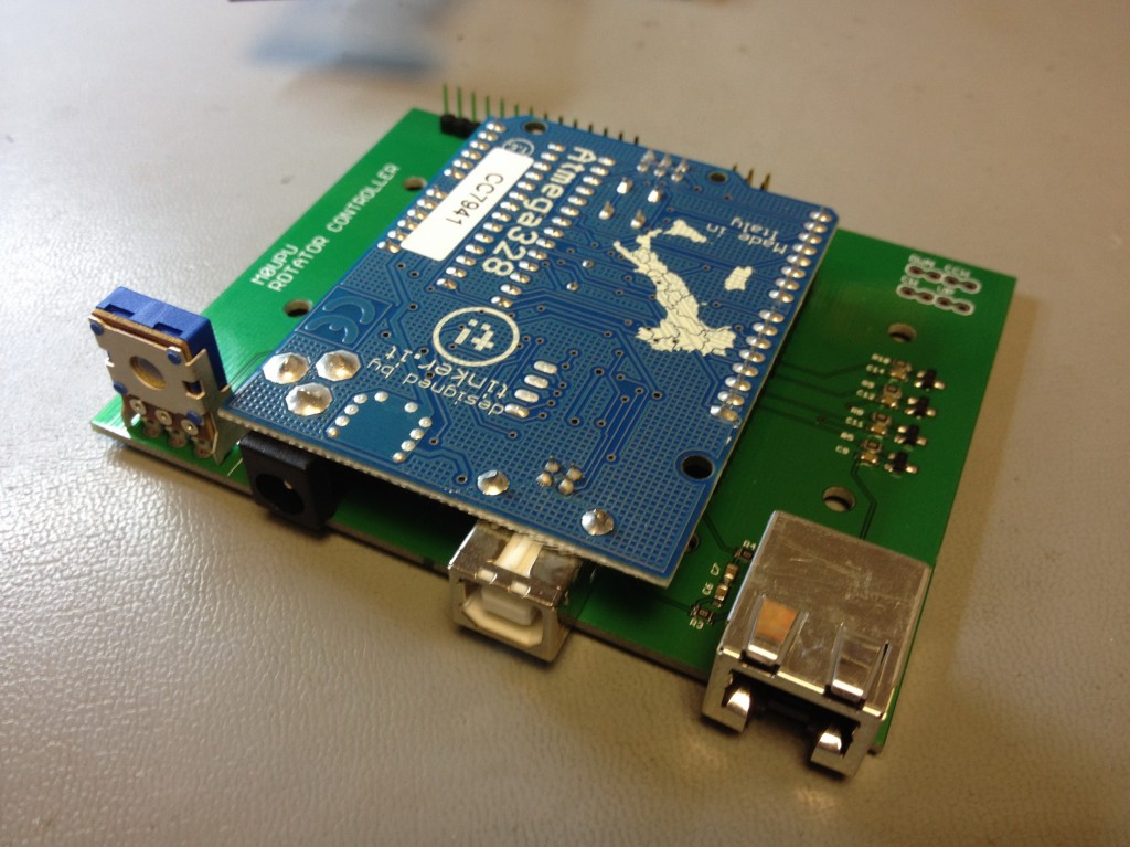
Here it is with an Uno installed :
And without :
Update 29/05/2017 :
We are no longer making this board. It was the last board we made by hand and we no longer have the resources to do this. Unfortunately its not viable at the price to get this board made externally therefore we are discontinuing it.
Update 05/05/2013 :
I’ve sold out of the first two batches of these rotator boards so I’ve placed an order for some new ones which should be delivered before the end of May. We took the opportunity to add a few improvements to the PCB. Its still based round the concept of plugging an Arduino Uno or Duemilanove in upside down as per the post below. Additionally we added the following improvements :
1/ LCD back light is linked to a PWM port so you can adjust the LCD back light brightness via code.
2/ Reset switch added.
3/ Added a remote power switch port (I use this to power a relay to turn the controller on see http://ava.upuaut.net/?p=461
4/ Broke out the I2C Ports
5/ Added LED indicators for the axis activations.
6/ Redesigned the board to accommodate changes.
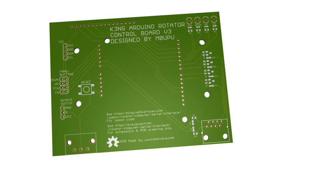
As before I plan to offer this PCB with the headers (RJ45 for rotator connection, Arduino headers and back light dimming resistor) and the switching circuits pre-assembled for about £25 including delivery (will confirm in the next few weeks).
You will need to supply reset switch/LED/LCD if you require these. Personally I use https://www.sparkfun.com/products/709 for the LCD.
This design has been released as open source the schematic is available for download here : K3NG Rotator Interface V3, the Cadsoft Eagle files here : K3NG Rotator Interface V3. Using the schematic and this image :
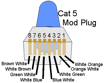
You should be able to wire a cable to match your particular rotator controller.
Original Article :
Given my ideal location for tracking on top of a hill I decided last year to beef up the Watson Collinear antenna I was using to a yagi. The only issue with this is the yagi antenna is directional and needs to be pointed at the target. To facilitate this I purchased a Yaesu G-5500 Elevation-Azimuth Rotator unit. This comes with a great controller that has a port on the back to plug in the optional GS-232A controller.
The only downside is the controller is a few hundred quid which given it can be emulated with an Arduino seemed a little bit excessive. Having spent a while searching round the web I came across K3NG’s Arduino Rotator Serial Interface which was by far and away the most complete code I’ve seen.
These days making PCB’s is so cheap thanks to Mitch at Hackvana I decided to make a board for the rotator controller hardware. Initially I was going to make a custom Arduino board with AVR on it etc but then I decided to make it easy and just put a header on there so you could plug an Arduino Uno/Duemilanove on there. This instantly gives you power, the serial interface and is replaceable quite easily.
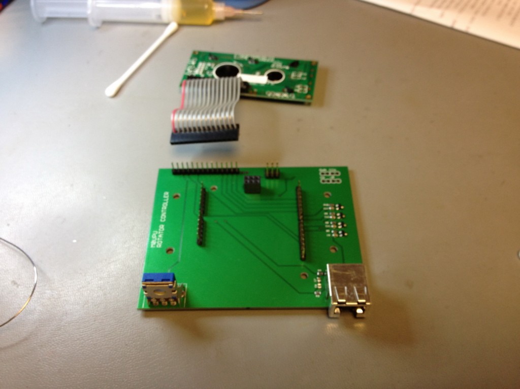
For the other components I used surface mount 0805 components and transistors. Connection to the rotator was via a CAT5 socket. The large pot on the left is to adjust the screen brightness. The header at the back is to connect an LCD too and there are 4 headers for physical up/down/left/right switches on there.
The Arduino goes in upside down :
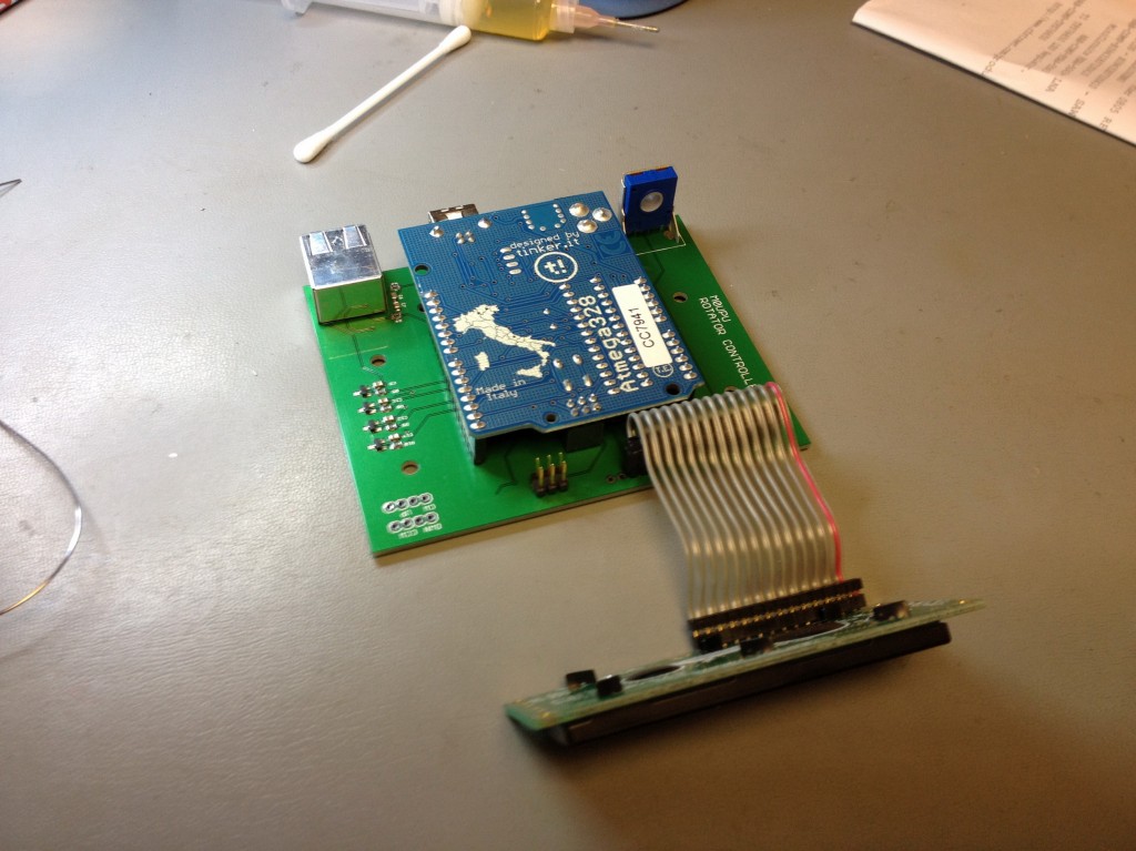
Then the LCD plugs in :
Finally it was designed to go in a Hammond enclosure :
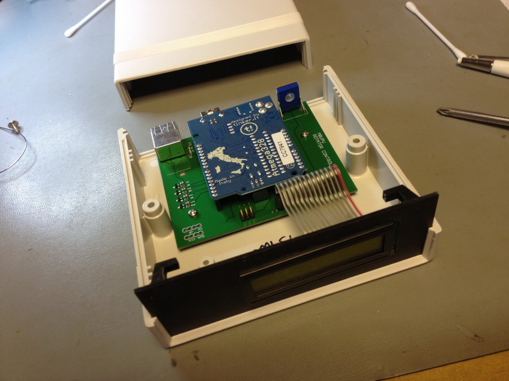
Add a 3D printed front bezel :
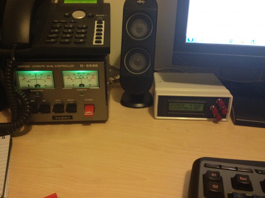
And voila a nice tidy interface for the controller that costs a damn sight less than the proper Yaesu thing. Now use K3NG’s wonderful code at http://radioartisan.wordpress.com/yaesu-rotator-computer-serial-interface/ to get it up and working.
I’ve released this board as Open Hardware so you are free to use it as you see fit. The Eagle CAD files are here : K3NG Rotator Interface V2
Bill of Materials for the board as follows :
Resistors : all 0805 1K Farnell 9332383
Capacitors : all 0805 0.1µF Farnell 1759143
Transistors : all MMBT2222A Farnell 9846700
RJ45 Jack : TE CONNECTIVITY 3-5338556-1 Farnell 2059819
Pot : TE CONNECTIVITY / CITEC 5350500107 Farnell 1174451
Header : Just buy strips of 1 row 2.54mm pitch header i.e Multicomp MC34743 Farnell 1593425
Case : Hammond 1598BSGYPBK Farnell 1426554
Just a quick warning I did originally intend to have the ICSP header broken out so you can program it via this but I didn’t have my spatial awareness hat on when I made the board and the lines are inverted so as it stands the ICSP break out isn’t usable (unless you plug it in from the rear of the board). This won’t affect you programming the Arduino as normal via the USB.
 As noted by James Coxon you can’t implement power saving mode until you have a lock. I also found engaging it before you had more than 5 satellites was problematic.
 F
F A
A