RTTY as discussed in Part 2 of these articles uses two tones a high and a low tone to convey the data. Whilst simple its performance can degrade as the signal gets weaker and with no error correction you may get packets with errors in them. To mitigate a little against this there is a more robust mode called DominoEX.
Note : This example should work with the original NTX2 but you may get significant drift as the temperature changes which will change the tone spacing and mean this doesn’t work . The NTX2B with its TCXO is more suitable.
DominoEX is an MFSK (Multiple frequency-shift keying) mode that uses 18 tones to transmit data, although there is no error correction built in the performance of DominoEX is such that its rarely needed. If you can hear the signal generally you can decode it. For a more in depth description please visit this page : http://www.qsl.net/zl1bpu/MFSK/DEX.htm
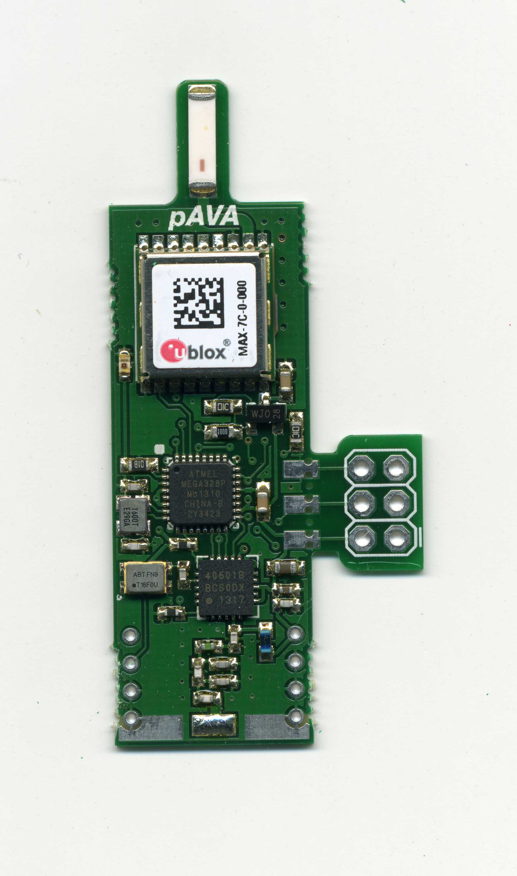
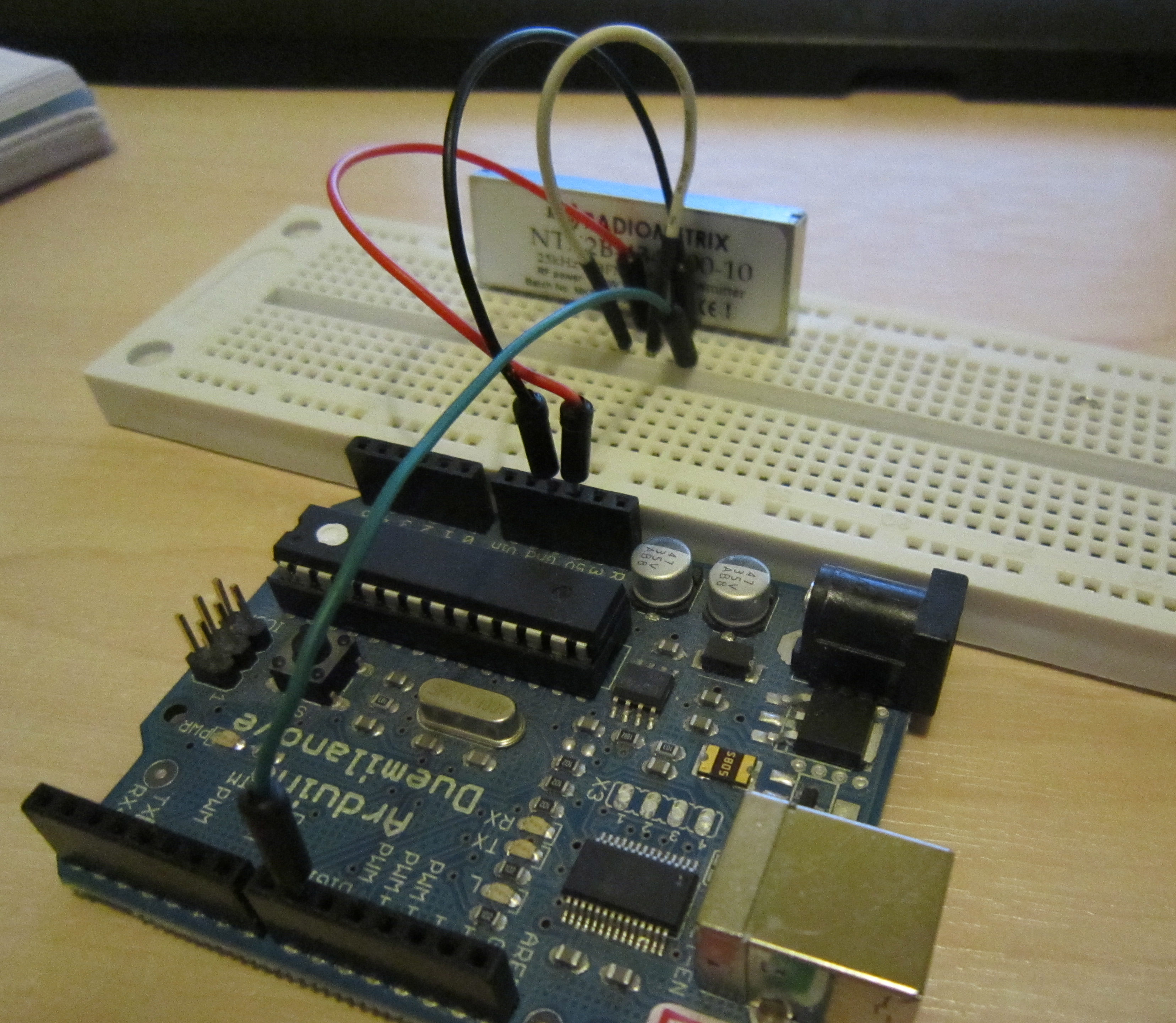
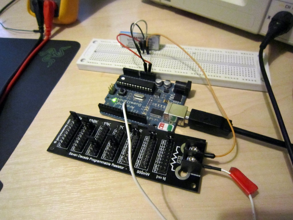
The key to DominoEX working is the distance between the tones has to be very precise. For DominoEX16 the baud rate has to be 15.625Hz. As you saw before our 8 bit Arduino doesn’t have the resolution to do this natively however we can increase the resolution of the Arduino by inserting a resistor between the Arduino pin 9 and the NTX2B TXD pin. The TXD pin has an internal 100k resistor so you’re making a voltage divider.
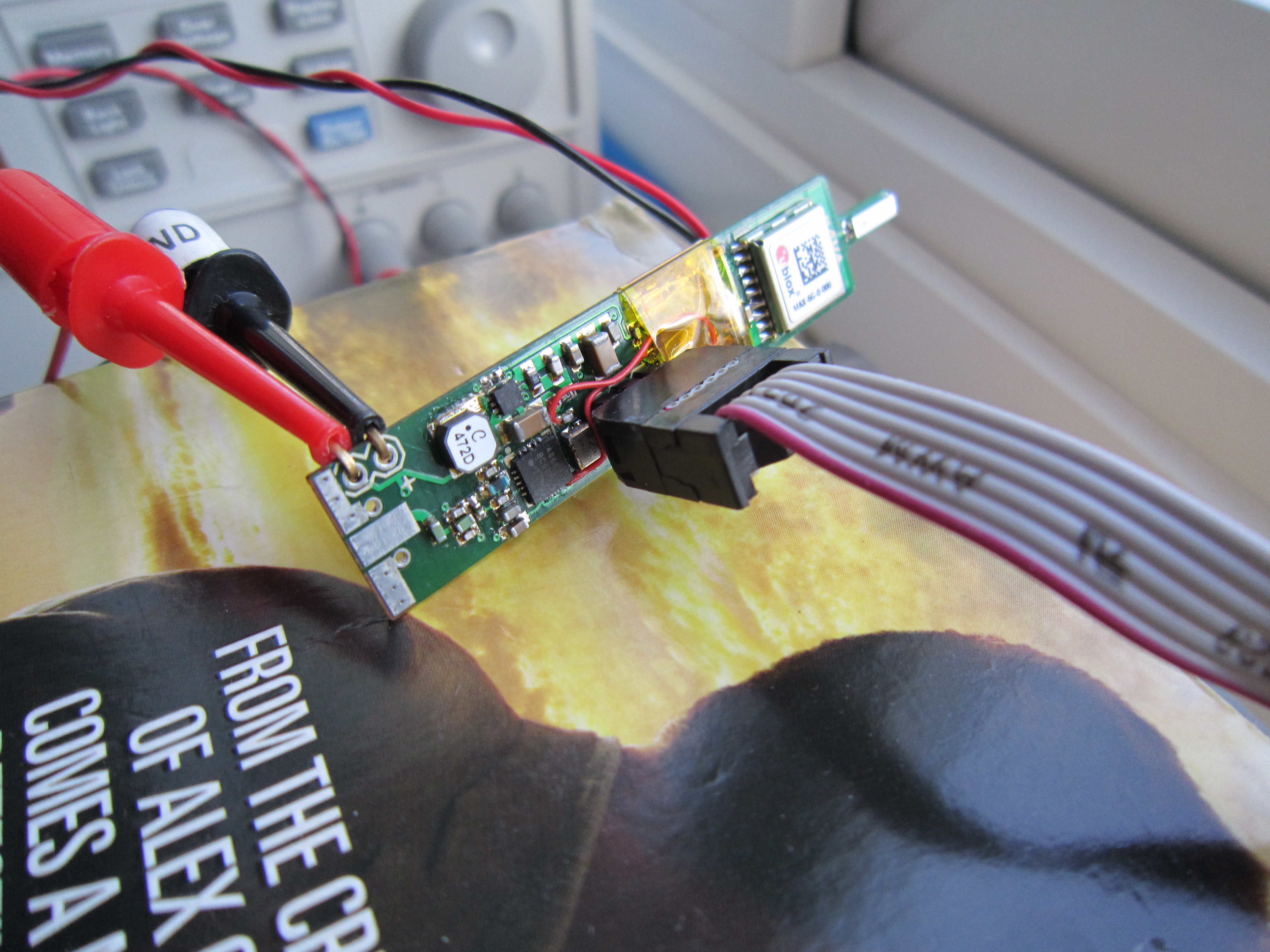
Using this method a 175k resistor means each PWM step gives the voltage needed to step the frequency up by the required amount. You may need to play with this to get the correct value. Here I’m using a Seven Decade Programmable resistor to test the values :
Code to test as follows :
/*
 Demo Code to Drive NTX2B via PWM
 DominoEX
 Written by Anthony Stirk M0UPU
 This example code is in the public domain.
 */

#define RADIOPIN 9

unsigned char varicode[][3] = {
 /* Primary alphabet */
 { 1,15, 9}, { 1,15,10}, { 1,15,11}, { 1,15,12}, { 1,15,13}, { 1,15,14}, { 1,15,15}, { 2, 8, 8},
 { 2,12, 0}, { 2, 8, 9}, { 2, 8,10}, { 2, 8,11}, { 2, 8,12}, { 2,13, 0}, { 2, 8,13}, { 2, 8,14},
 { 2, 8,15}, { 2, 9, 8}, { 2, 9, 9}, { 2, 9,10}, { 2, 9,11}, { 2, 9,12}, { 2, 9,13}, { 2, 9,14},
 { 2, 9,15}, { 2,10, 8}, { 2,10, 9}, { 2,10,10}, { 2,10,11}, { 2,10,12}, { 2,10,13}, { 2,10,14},
 { 0, 0, 0}, { 7,11, 0}, { 0, 8,14}, { 0,10,11}, { 0, 9,10}, { 0, 9, 9}, { 0, 8,15}, { 7,10, 0},
 { 0, 8,12}, { 0, 8,11}, { 0, 9,13}, { 0, 8, 8}, { 2,11, 0}, { 7,14, 0}, { 7,13, 0}, { 0, 8, 9},
 { 3,15, 0}, { 4,10, 0}, { 4,15, 0}, { 5, 9, 0}, { 6, 8, 0}, { 5,12, 0}, { 5,14, 0}, { 6,12, 0},
 { 6,11, 0}, { 6,14, 0}, { 0, 8,10}, { 0, 8,13}, { 0,10, 8}, { 7,15, 0}, { 0, 9,15}, { 7,12, 0},
 { 0, 9, 8}, { 3, 9, 0}, { 4,14, 0}, { 3,12, 0}, { 3,14, 0}, { 3, 8, 0}, { 4,12, 0}, { 5, 8, 0},
 { 5,10, 0}, { 3,10, 0}, { 7, 8, 0}, { 6,10, 0}, { 4,11, 0}, { 4, 8, 0}, { 4,13, 0}, { 3,11, 0},
 { 4, 9, 0}, { 6,15, 0}, { 3,13, 0}, { 2,15, 0}, { 2,14, 0}, { 5,11, 0}, { 6,13, 0}, { 5,13, 0},
 { 5,15, 0}, { 6, 9, 0}, { 7, 9, 0}, { 0,10,14}, { 0,10, 9}, { 0,10,15}, { 0,10,10}, { 0, 9,12},
 { 0, 9,11}, { 4, 0, 0}, { 1,11, 0}, { 0,12, 0}, { 0,11, 0}, { 1, 0, 0}, { 0,15, 0}, { 1, 9, 0},
 { 0,10, 0}, { 5, 0, 0}, { 2,10, 0}, { 1,14, 0}, { 0, 9, 0}, { 0,14, 0}, { 6, 0, 0}, { 3, 0, 0},
 { 1, 8, 0}, { 2, 8, 0}, { 7, 0, 0}, { 0, 8, 0}, { 2, 0, 0}, { 0,13, 0}, { 1,13, 0}, { 1,12, 0},
 { 1,15, 0}, { 1,10, 0}, { 2, 9, 0}, { 0,10,12}, { 0, 9,14}, { 0,10,12}, { 0,11, 8}, { 2,10,15},
 { 2,11, 8}, { 2,11, 9}, { 2,11,10}, { 2,11,11}, { 2,11,12}, { 2,11,13}, { 2,11,14}, { 2,11,15},
 { 2,12, 8}, { 2,12, 9}, { 2,12,10}, { 2,12,11}, { 2,12,12}, { 2,12,13}, { 2,12,14}, { 2,12,15},
 { 2,13, 8}, { 2,13, 9}, { 2,13,10}, { 2,13,11}, { 2,13,12}, { 2,13,13}, { 2,13,14}, { 2,13,15},
 { 2,14, 8}, { 2,14, 9}, { 2,14,10}, { 2,14,11}, { 2,14,12}, { 2,14,13}, { 2,14,14}, { 2,14,15},
 { 0,11, 9}, { 0,11,10}, { 0,11,11}, { 0,11,12}, { 0,11,13}, { 0,11,14}, { 0,11,15}, { 0,12, 8},
 { 0,12, 9}, { 0,12,10}, { 0,12,11}, { 0,12,12}, { 0,12,13}, { 0,12,14}, { 0,12,15}, { 0,13, 8},
 { 0,13, 9}, { 0,13,10}, { 0,13,11}, { 0,13,12}, { 0,13,13}, { 0,13,14}, { 0,13,15}, { 0,14, 8},
 { 0,14, 9}, { 0,14,10}, { 0,14,11}, { 0,14,12}, { 0,14,13}, { 0,14,14}, { 0,14,15}, { 0,15, 8},
 { 0,15, 9}, { 0,15,10}, { 0,15,11}, { 0,15,12}, { 0,15,13}, { 0,15,14}, { 0,15,15}, { 1, 8, 8},
 { 1, 8, 9}, { 1, 8,10}, { 1, 8,11}, { 1, 8,12}, { 1, 8,13}, { 1, 8,14}, { 1, 8,15}, { 1, 9, 8},
 { 1, 9, 9}, { 1, 9,10}, { 1, 9,11}, { 1, 9,12}, { 1, 9,13}, { 1, 9,14}, { 1, 9,15}, { 1,10, 8},
 { 1,10, 9}, { 1,10,10}, { 1,10,11}, { 1,10,12}, { 1,10,13}, { 1,10,14}, { 1,10,15}, { 1,11, 8},
 { 1,11, 9}, { 1,11,10}, { 1,11,11}, { 1,11,12}, { 1,11,13}, { 1,11,14}, { 1,11,15}, { 1,12, 8},
 { 1,12, 9}, { 1,12,10}, { 1,12,11}, { 1,12,12}, { 1,12,13}, { 1,12,14}, { 1,12,15}, { 1,13, 8},
 { 1,13, 9}, { 1,13,10}, { 1,13,11}, { 1,13,12}, { 1,13,13}, { 1,13,14}, { 1,13,15}, { 1,14, 8},
 { 1,14, 9}, { 1,14,10}, { 1,14,11}, { 1,14,12}, { 1,14,13}, { 1,14,14}, { 1,14,15}, { 1,15, 8},

/* Secondary alphabet */
 { 6,15, 9}, { 6,15,10}, { 6,15,11}, { 6,15,12}, { 6,15,13}, { 6,15,14}, { 6,15,15}, { 7, 8, 8},
 { 4,10,12}, { 7, 8, 9}, { 7, 8,10}, { 7, 8,11}, { 7, 8,12}, { 4,10,13}, { 7, 8,13}, { 7, 8,14},
 { 7, 8,15}, { 7, 9, 8}, { 7, 9, 9}, { 7, 9,10}, { 7, 9,11}, { 7, 9,12}, { 7, 9,13}, { 7, 9,14},
 { 7, 9,15}, { 7,10, 8}, { 7,10, 9}, { 7,10,10}, { 7,10,11}, { 7,10,12}, { 7,10,13}, { 7,10,14},
 { 3, 8, 8}, { 4,15,11}, { 5, 8,14}, { 5,10,11}, { 5, 9,10}, { 5, 9, 9}, { 5, 8,15}, { 4,15,10},
 { 5, 8,12}, { 5, 8,11}, { 5, 9,13}, { 5, 8, 8}, { 4,10,11}, { 4,15,14}, { 4,15,13}, { 5, 8, 9},
 { 4,11,15}, { 4,12,10}, { 4,12,15}, { 4,13, 9}, { 4,14, 8}, { 4,13,12}, { 4,13,14}, { 4,14,12},
 { 4,14,11}, { 4,14,14}, { 5, 8,10}, { 5, 8,13}, { 5,10, 8}, { 4,15,15}, { 5, 9,15}, { 4,15,12},
 { 5, 9, 8}, { 4,11, 9}, { 4,12,14}, { 4,11,12}, { 4,11,14}, { 4,11, 8}, { 4,12,12}, { 4,13, 8},
 { 4,13,10}, { 4,11,10}, { 4,15, 8}, { 4,14,10}, { 4,12,11}, { 4,12, 8}, { 4,12,13}, { 4,11,11},
 { 4,12, 9}, { 4,14,15}, { 4,11,13}, { 4,10,15}, { 4,10,14}, { 4,13,11}, { 4,14,13}, { 4,13,13},
 { 4,13,15}, { 4,14, 9}, { 4,15, 9}, { 5,10,14}, { 5,10, 9}, { 5,10,15}, { 5,10,10}, { 5, 9,12},
 { 5, 9,11}, { 3, 8,12}, { 4, 9,11}, { 4, 8,12}, { 4, 8,11}, { 3, 8, 9}, { 4, 8,15}, { 4, 9, 9},
 { 4, 8,10}, { 3, 8,13}, { 4,10,10}, { 4, 9,14}, { 4, 8, 9}, { 4, 8,14}, { 3, 8,14}, { 3, 8,11},
 { 4, 9, 8}, { 4,10, 8}, { 3, 8,15}, { 4, 8, 8}, { 3, 8,10}, { 4, 8,13}, { 4, 9,13}, { 4, 9,12},
 { 4, 9,15}, { 4, 9,10}, { 4,10, 9}, { 5,10,12}, { 5, 9,14}, { 5,10,12}, { 5,11, 8}, { 7,10,15},
 { 7,11, 8}, { 7,11, 9}, { 7,11,10}, { 7,11,11}, { 7,11,12}, { 7,11,13}, { 7,11,14}, { 7,11,15},
 { 7,12, 8}, { 7,12, 9}, { 7,12,10}, { 7,12,11}, { 7,12,12}, { 7,12,13}, { 7,12,14}, { 7,12,15},
 { 7,13, 8}, { 7,13, 9}, { 7,13,10}, { 7,13,11}, { 7,13,12}, { 7,13,13}, { 7,13,14}, { 7,13,15},
 { 7,14, 8}, { 7,14, 9}, { 7,14,10}, { 7,14,11}, { 7,14,12}, { 7,14,13}, { 7,14,14}, { 7,14,15},
 { 5,11, 9}, { 5,11,10}, { 5,11,11}, { 5,11,12}, { 5,11,13}, { 5,11,14}, { 5,11,15}, { 5,12, 8},
 { 5,12, 9}, { 5,12,10}, { 5,12,11}, { 5,12,12}, { 5,12,13}, { 5,12,14}, { 5,12,15}, { 5,13, 8},
 { 5,13, 9}, { 5,13,10}, { 5,13,11}, { 5,13,12}, { 5,13,13}, { 5,13,14}, { 5,13,15}, { 5,14, 8},
 { 5,14, 9}, { 5,14,10}, { 5,14,11}, { 5,14,12}, { 5,14,13}, { 5,14,14}, { 5,14,15}, { 5,15, 8},
 { 5,15, 9}, { 5,15,10}, { 5,15,11}, { 5,15,12}, { 5,15,13}, { 5,15,14}, { 5,15,15}, { 6, 8, 8},
 { 6, 8, 9}, { 6, 8,10}, { 6, 8,11}, { 6, 8,12}, { 6, 8,13}, { 6, 8,14}, { 6, 8,15}, { 6, 9, 8},
 { 6, 9, 9}, { 6, 9,10}, { 6, 9,11}, { 6, 9,12}, { 6, 9,13}, { 6, 9,14}, { 6, 9,15}, { 6,10, 8},
 { 6,10, 9}, { 6,10,10}, { 6,10,11}, { 6,10,12}, { 6,10,13}, { 6,10,14}, { 6,10,15}, { 6,11, 8},
 { 6,11, 9}, { 6,11,10}, { 6,11,11}, { 6,11,12}, { 6,11,13}, { 6,11,14}, { 6,11,15}, { 6,12, 8},
 { 6,12, 9}, { 6,12,10}, { 6,12,11}, { 6,12,12}, { 6,12,13}, { 6,12,14}, { 6,12,15}, { 6,13, 8},
 { 6,13, 9}, { 6,13,10}, { 6,13,11}, { 6,13,12}, { 6,13,13}, { 6,13,14}, { 6,13,15}, { 6,14, 8},
 { 6,14, 9}, { 6,14,10}, { 6,14,11}, { 6,14,12}, { 6,14,13}, { 6,14,14}, { 6,14,15}, { 6,15, 8},
};
uint8_t _sym = 0;

void setup() {
 pinMode(RADIOPIN, OUTPUT);
 setPwmFrequency(RADIOPIN, 1);
}

// the loop routine runs over and over again forever:
void loop() {
dominoex_string("M0UPU DOMINOEX TEST\n");

}
void dominoex_txsym(uint8_t sym)
{
 _sym = (_sym + 2 + sym) % 18;
 analogWrite(RADIOPIN, _sym);
 delay(64);
}
void dominoex_txchar(uint16_t vcode)
{
 uint8_t i, c;

 for(i = 0; i < 3; i++)
 {
 c = varicode[vcode][i];
 if(i && !(c & 0x8)) break;
 dominoex_txsym(c);
 }
}
void dominoex_string(char *s)
{
 for(; *s; s++) dominoex_txchar(*s);
}

void setPwmFrequency(int pin, int divisor) {
 byte mode;
 if(pin == 5 || pin == 6 || pin == 9 || pin == 10) {
 switch(divisor) {
 case 1:
 mode = 0x01;
 break;
 case 8:
 mode = 0x02;
 break;
 case 64:
 mode = 0x03;
 break;
 case 256:
 mode = 0x04;
 break;
 case 1024:
 mode = 0x05;
 break;
 default:
 return;
 }
 if(pin == 5 || pin == 6) {
 TCCR0B = TCCR0B & 0b11111000 | mode;
 }
 else {
 TCCR1B = TCCR1B & 0b11111000 | mode;
 }
 }
 else if(pin == 3 || pin == 11) {
 switch(divisor) {
 case 1:
 mode = 0x01;
 break;
 case 8:
 mode = 0x02;
 break;
 case 32:
 mode = 0x03;
 break;
 case 64:
 mode = 0x04;
 break;
 case 128:
 mode = 0x05;
 break;
 case 256:
 mode = 0x06;
 break;
 case 1024:
 mode = 0x7;
 break;
 default:
 return;
 }
 TCCR2B = TCCR2B & 0b11111000 | mode;
 }
}
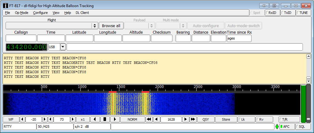
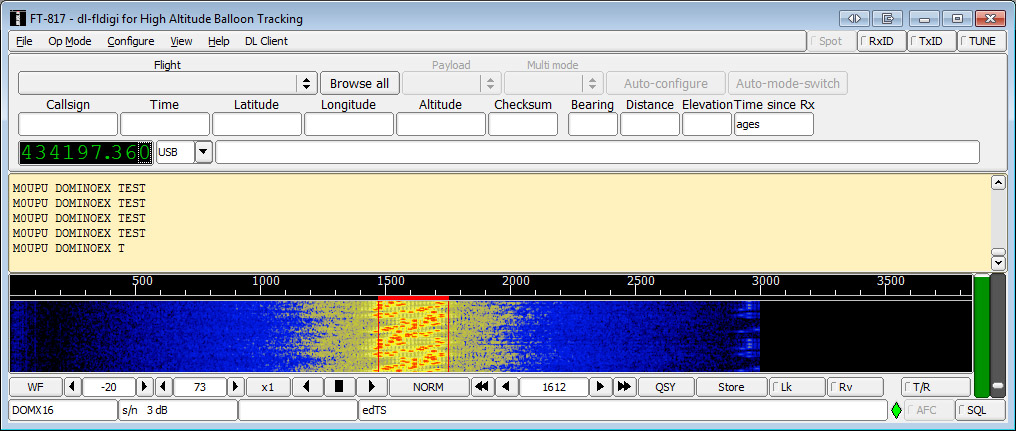
Viewed in DL-FLDIGI (Click Op Mode -> DominoEX -> DominoEX16)
You can adjust the code to do DominoEX22 by amending the delay line from 64 ( 1/Baud rate so for DominoEX16 = 0.064s, DominoEX22 = 1/21.533 = 0.0464) to 46 and adjusting the resistor to ~ 100k.
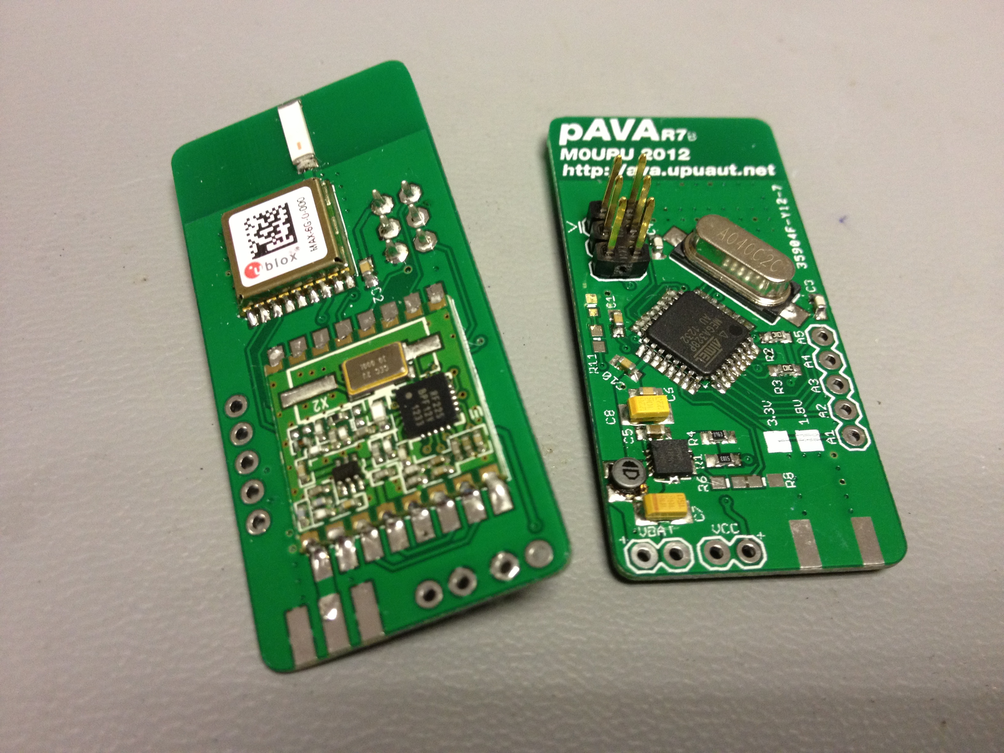
You can purchase the NTX2B at Hab Supplies here : http://ava.upuaut.net/store/index.php?route=product/product&path=71_63&product_id=92

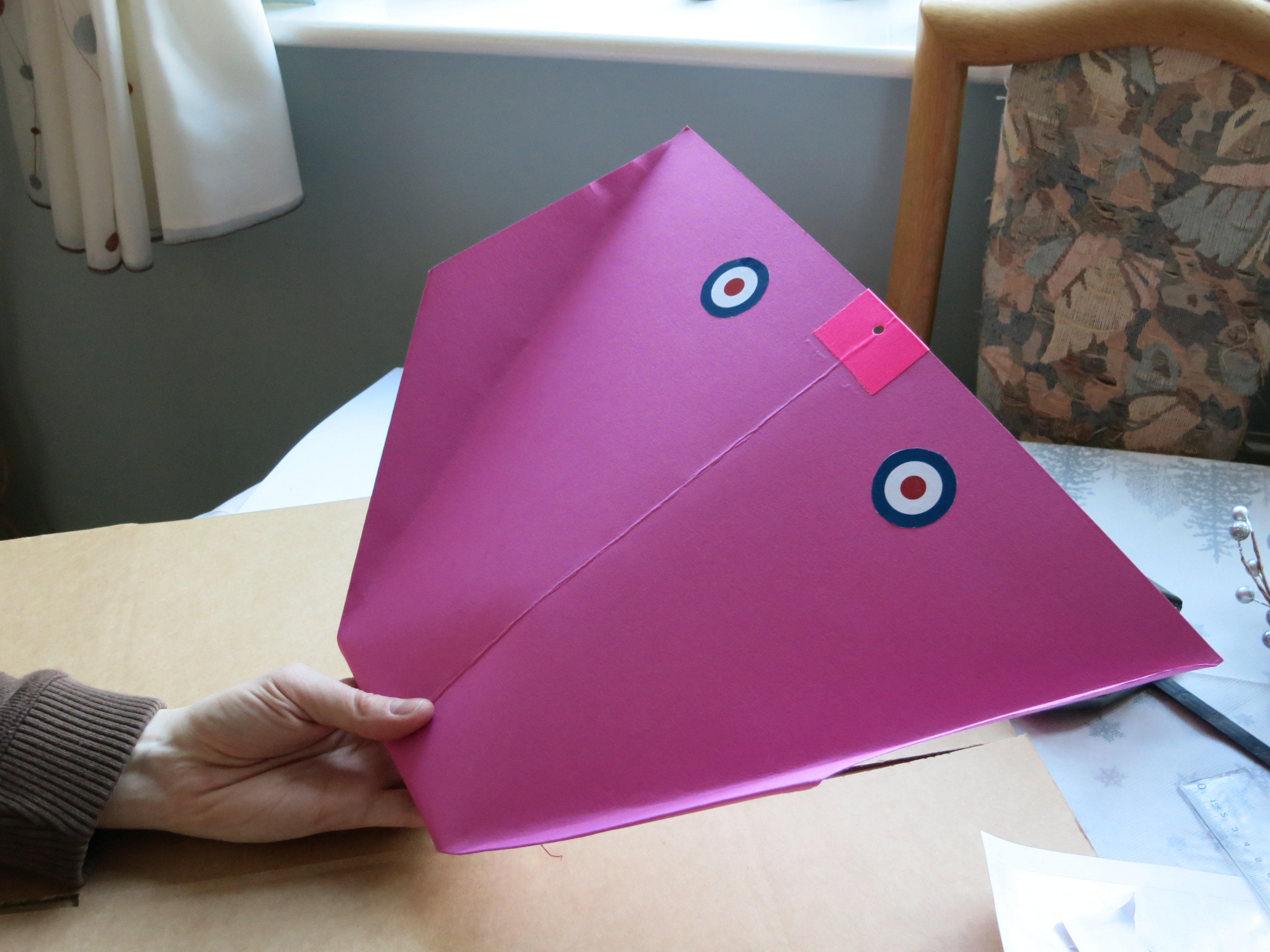
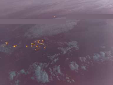
 The weather on Saturday was very changeable. Initially I called the launch off but around lunch time the clouds cleared although the wind didn’t subside.The predicted path looked too good to waste so I took chance. With 1.5g of free lift the 36″ Qualatex balloon didn’t look inflated at all.
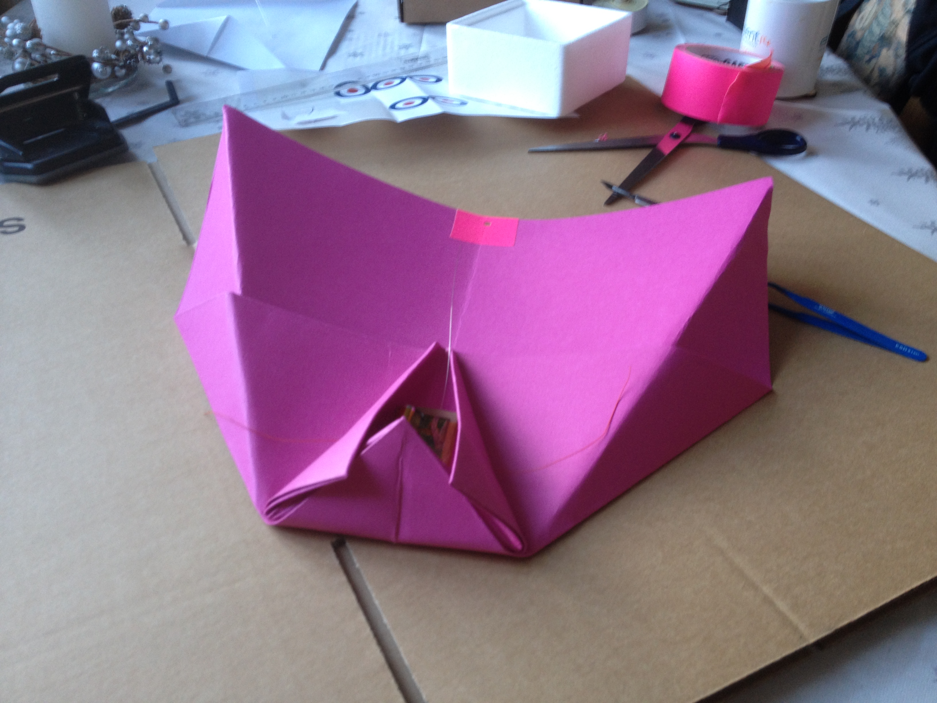
 I seem to be getting quite good at the “unintentionally sketchy launch”. The balloons ascent was interesting to say the least but up was up even if it did contain small amounts of down on the way.
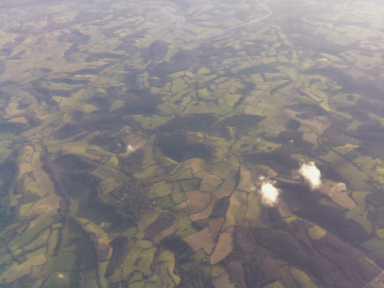
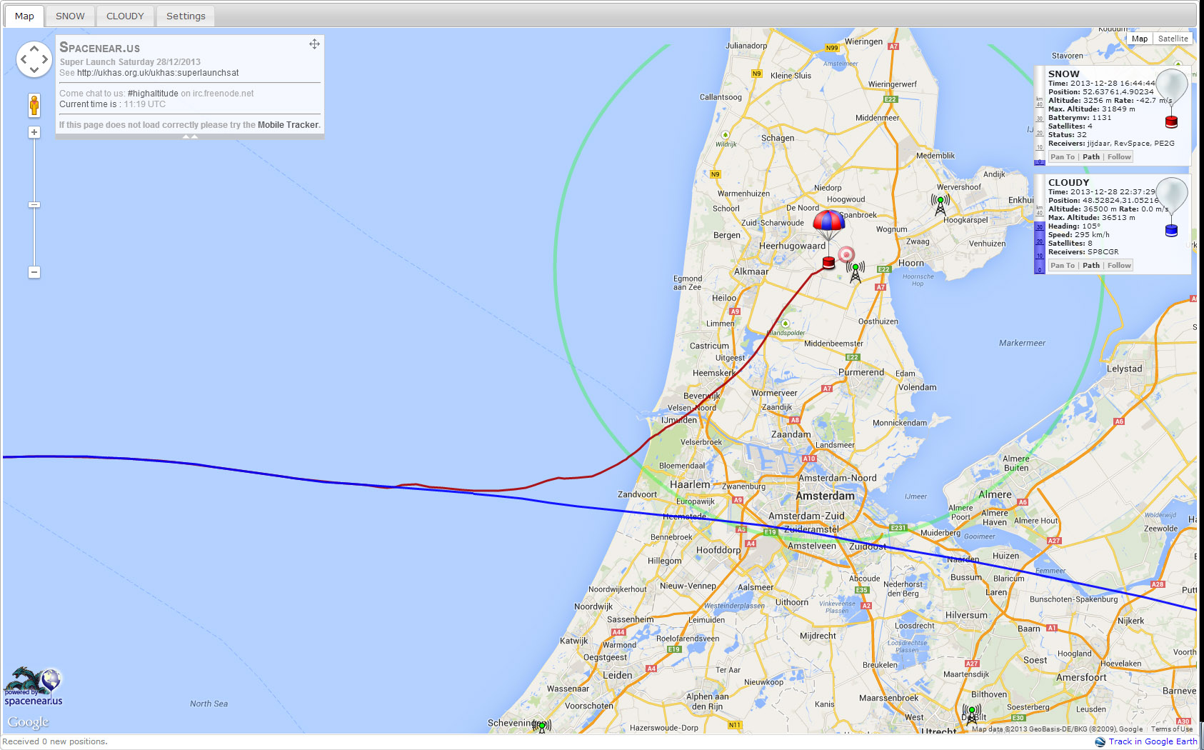
 Battery data, speed and attitude over the flight (Thanks to x-f for this)