PAVA R7 Further Power Saving

Due to a cock up with the design (I’d left copper pour under the GPS antenna so no lock) I had to get some more PCB’s made. Given how many of these seem to be ending in the sea and how you can’t see design cockups on black PCB’s I decided to go with plain old boring green for PAVA R7b. However they look quite nice :

2012-12-27 14.25.18

Specs as before with the small addition of a 1.8V LED for status reporting as needed.

Testing last week with the 3.3V board under the following conditions : continuous TX @ 11dB , input voltage 1.58v with no power saving code saw a average draw of 254mA from the battery. This equates to about 12 hours run time from a single AA. Implementing power saving code, turning off the ADC and putting the GPS in 1 second cyclic mode brought this down to 148mA increasing run time to about 20 hours from an AA.

Now the 1.8V boards are here I ran the same power saving code under the same conditions. The result is an average draw, once lock has been attained, of 66mA from the battery. This equates to theoretical 45 hour + run time from a single AA. It may be more as it seems to use less power the more satellites it has, this maybe offset against the temperature however. Look ma no power :IMG_1380As noted by James Coxon you can’t implement power saving mode until you have a lock. I also found engaging it before you had more than 5 satellites was problematic.

I was unable to get anything other than the default 1 second cyclic mode working. In fact amending the cyclic to anything other than default seemed to cause issues, the clock stopped counting and the module started behaving erratically. However just turning cyclic mode on with no other changes seems to work.

void setGPS_PowerSaveMode() {
 // Power Save Mode
 uint8_t setPSM[] = {
 0xB5, 0x62, 0x06, 0x11, 0x02, 0x00, 0x08, 0x01, 0x22, 0x92 }; // Setup for Power Save Mode (Default Cyclic 1s)
 sendUBX(setPSM, sizeof(setPSM)/sizeof(uint8_t));
}

The following code may be useful as well :

<pre>
void setGps_MaxPerformanceMode() {
 //Set GPS for Max Performance Mode
 uint8_t setMax[] = {
 0xB5, 0x62, 0x06, 0x11, 0x02, 0x00, 0x08, 0x00, 0x21, 0x91 }; // Setup for Max Power Mode
 sendUBX(setMax, sizeof(setMax)/sizeof(uint8_t));
}
void resetGPS() { // Cold Boot GPS
 uint8_t set_reset[] = {
 0xB5, 0x62, 0x06, 0x04, 0x04, 0x00, 0xFF, 0x87, 0x00, 0x00, 0x94, 0xF5 };
 sendUBX(set_reset, sizeof(set_reset)/sizeof(uint8_t));
}

Launch PAVA & SPEARS!

Had a bitter sweet weekend. Finally got round to launching the dual Ublox & Adafruit GPS payload to ascertain if the Adafruit module works above its previous limit of 27km. Unfortunately the balloon burst prematurely at about 37km and landed in the English Channel. Still proved the PAVA boards work and the Adafruit is good to at least that.

On Saturday we did a launch with The Register, a second PAVA board with the new interrupt driven code providing telemetry as $$TRUSS. This worked flawlessly right up until it landed in the English Channel (spot the pattern ?)

Lester writes it up better than I ever could so head over here and have a read.

http://www.theregister.co.uk/2012/12/04/spears_flight/

Mark my works English Channel we will be back…

Coding : Interrupt Driven RTTY Transmission on Arduino/AVR

One of the things on my to-do list has been convert the transmission of the RTTY into the background as an interrupt. When the payload is transmitting at 50 baud it effectively sits around doing nothing for 15 seconds whilst it transmits.

By moving this to an interrupt based routine it can transmit in the background whilst allowing the foreground  tasks to run. This means more data being logged, more accurate altitude measurements, faster response to a burst if needed etc.

Having had a good read of http://www.engblaze.com/microcontroller-tutorial-avr-and-arduino-timer-interrupts/ I set about coding up the code to do this one step at a time. Firstly I replicated the high/low code from http://ukhas.org.uk/guides:linkingarduinotontx2#part_1_-_test_circuit_and_test_code

After finding a few code timing errors I think I’ve sorted it out so it runs as a stand alone procedure which TX’s in the back ground. The RFM22B seemed to struggle to switch frequencies fast enough above 300 baud using radio1.setFrequency(RADIO_FREQUENCY_LOW)/radio1.setFrequency(RADIO_FREQUENCY_HIGH). Dave Akerman suggested (as recommended by Navrac) that using the shift frequency register is better way. Indeed it is much faster, results in a much cleaner signal and allowed the baud rate to decode fine up to 600.

So here is what I’ve come up with, it will need further testing and integration into my existing flight code.


/*
 Interrupt Driven RTTY TX Demo
 
 Transmits data via RTTY with an interupt driven subroutine.
 
 By Anthony Stirk M0UPU 
 
 October 2012 Version 5
 
 Thanks and credits :
 Evolved from Rob Harrison's RTTY Code.
 Compare match register calculation by Phil Heron.
 Thanks to : http://www.engblaze.com/microcontroller-tutorial-avr-and-arduino-timer-interrupts/
 RFM22B Code from James Coxon http://ukhas.org.uk/guides:rfm22b 
 Suggestion to use Frequency Shift Registers by Dave Akerman (Daveake)/Richard Cresswell (Navrac)
 
 This program is free software: you can redistribute it and/or modify
 it under the terms of the GNU General Public License as published by
 the Free Software Foundation, either version 3 of the License, or
 (at your option) any later version.
 
 This program is distributed in the hope that it will be useful,
 but WITHOUT ANY WARRANTY; without even the implied warranty of
 MERCHANTABILITY or FITNESS FOR A PARTICULAR PURPOSE.  See the
 GNU General Public License for more details.
 
 See <http://www.gnu.org/licenses/>.
 */
#include <avr/io.h>
#include <avr/interrupt.h>
#include <util/crc16.h>
#include <SPI.h>
#include <RFM22.h>

#define ASCII 7          // ASCII 7 or 8
#define STOPBITS 2       // Either 1 or 2
#define TXDELAY 0        // Delay between sentence TX's
#define RTTY_BAUD 100    // Baud rate for use with RFM22B Max = 600
#define RADIO_FREQUENCY 434.198


#define RFM22B_SDN 3
#define RFM22B_PIN 10

char datastring[80];
char txstring[80];
volatile int txstatus=1;
volatile int txstringlength=0;
volatile char txc;
volatile int txi;
volatile int txj;
unsigned int count=0;


rfm22 radio1(RFM22B_PIN);

void setup()
{
  initialise_interrupt();
  setupRadio();
}

void loop()
{

  sprintf(datastring,"$$$$$M0UPU,%04u,RTTY TEST BEACON RTTY TEST BEACON",count); // Puts the text in the datastring
  unsigned int CHECKSUM = gps_CRC16_checksum(datastring);  // Calculates the checksum for this datastring
  char checksum_str[6];
  sprintf(checksum_str, "*%04X\n", CHECKSUM);
  strcat(datastring,checksum_str);
  delay(1000);
  count++;
}

ISR(TIMER1_COMPA_vect)
{
  switch(txstatus) {
  case 0: // This is the optional delay between transmissions.
    txj++;
    if(txj>(TXDELAY*RTTY_BAUD)) { 
      txj=0;
      txstatus=1;
    }
    break;
  case 1: // Initialise transmission, take a copy of the string so it doesn't change mid transmission. 
    strcpy(txstring,datastring);
    txstringlength=strlen(txstring);
    txstatus=2;
    txj=0;
    break;
  case 2: // Grab a char and lets go transmit it. 
    if ( txj < txstringlength)
    {
      txc = txstring[txj];
      txj++;
      txstatus=3;
      rtty_txbit (0); // Start Bit;
      txi=0;
    }
    else 
    {
      txstatus=0; // Should be finished
      txj=0;
    }
    break;
  case 3:
    if(txi<ASCII)
    {
      txi++;
      if (txc & 1) rtty_txbit(1); 
      else rtty_txbit(0);	
      txc = txc >> 1;
      break;
    }
    else 
    {
      rtty_txbit (1); // Stop Bit
      txstatus=4;
      txi=0;
      break;
    } 
  case 4:
    if(STOPBITS==2)
    {
      rtty_txbit (1); // Stop Bit
      txstatus=2;
      break;
    }
    else
    {
      txstatus=2;
      break;
    }

  }
}

void rtty_txbit (int bit)
{
  if (bit)
  {
    radio1.write(0x73,0x03); // High
  }
  else
  {
    radio1.write(0x73,0x00); // Low
  }
}

void setupRadio(){
  pinMode(RFM22B_SDN, OUTPUT);    // RFM22B SDN is on ARDUINO A3
  digitalWrite(RFM22B_SDN, LOW);
  delay(1000);
  rfm22::initSPI();
  radio1.init();
  radio1.write(0x71, 0x00); // unmodulated carrier
  //This sets up the GPIOs to automatically switch the antenna depending on Tx or Rx state, only needs to be done at start up
  radio1.write(0x0b,0x12);
  radio1.write(0x0c,0x15);
  radio1.setFrequency(RADIO_FREQUENCY);
  radio1.write(0x6D, 0x04);// turn tx low power 11db
  radio1.write(0x07, 0x08);
  delay(500);
}

uint16_t gps_CRC16_checksum (char *string)
{
  size_t i;
  uint16_t crc;
  uint8_t c;

  crc = 0xFFFF;

  // Calculate checksum ignoring the first two $s
  for (i = 5; i < strlen(string); i++)
  {
    c = string[i];
    crc = _crc_xmodem_update (crc, c);
  }

  return crc;
}    
void initialise_interrupt() 
{
  // initialize Timer1
  cli();          // disable global interrupts
  TCCR1A = 0;     // set entire TCCR1A register to 0
  TCCR1B = 0;     // same for TCCR1B
  OCR1A = F_CPU / 1024 / RTTY_BAUD - 1;  // set compare match register to desired timer count:
  TCCR1B |= (1 << WGM12);   // turn on CTC mode:
  // Set CS10 and CS12 bits for:
  TCCR1B |= (1 << CS10);
  TCCR1B |= (1 << CS12);
  // enable timer compare interrupt:
  TIMSK1 |= (1 << OCIE1A);
  sei();          // enable global interrupts
}

picoAva sealed and ready to fly..and very pink

I’ve been asked by Adafruit to test their Ultimate GPS Module to ascertain if the new firmware operates up to and above 40km in altitude. It seemed like a good opportunity to test the new pAVAR6 boards at the same time.

After some coding I put the Adafruit module on A1 and A2 and used software serial to read this and the hardware UARTS to read the Ublox module. Software serial is never brilliant so the code just waits a second or two, if it doesn’t get a valid sentence from the Adafruit module it just carries on. (Software serial uses interrupts which have to be turned off to transmit RTTY)

To differentiate between the two GPS modules the payload transmits two call signs, $$PAVA which is the data from the Ublox module and $$QAVA which is data from the Adafruit module. Power comes from pAVA’s on board DC-DC Boost converter  under testing it has enough grunt to power both modules and achieved 11 hours run time from a single Energizer Lithium AA battery.

To keep everything together a 10 cms polystyrene ball was cut into 3 slices. On the bottom one I constructed a quarter wave antenna from solid core wire and some drinking straws :

The middle section was then hollowed out to make space for the Adafruit module, the pAVAR6 board and a single Energizer Lithium. For testing wires from the battery and from the board power connection were routed externally :

Everything was glued in place with copious amounts of hot glue. Finally some pink cord was inserted and the top piece was glued on :

Finally some bright pink paint (thx www.daveakerman.com) finished the job off looking like some sort of camp death star (will use a lighter pen to mark for cutting next time!) :

All glued up nothing moves around to power the payload up you can connect external power to it, for flight I will just solder the battery wires to the payload wires externally. Finally the weight, this payload with everything in and 2 GPS modules comes in at fractionally more than 50g :

 Just need the weather to sort itself out so I can launch this now!

Low powered tracker 1.8V 4Mhz “Arduino”

Update : The run time for the 1.8V 4Mhz board was 27.5 hours vs 13 hours for the 3.3V 8Mhz version. This is a huge difference and we haven’t even started on power saving modes in software yet. 

The new pAVA R6 board was designed with the ability to be able to run the logic at 1.8V if fitted with the correct regulator. Hopefully this will save even more power, as I write this the board is current on test with the same code that powered the 3.3V version for 13 hours from a single AA.

In order to drop the voltage to 1.8V for the board a few small changes had to be made, primarily the ATMega328P has to run at 4Mhz as opposed to 8Mhz to stay in spec. Secondly the uBLOX MAX6Q module has to be switched out for the 1.8V rated MAX6G module. The RFM22B is fine down to 1.8V.

So fitted with a 4Mhz crystal and a TPS61200DRC regulator the board has been tested step by step this week to ensure the AVR works, then the radio and finally the GPS. Although I utilise the Arduino enviroment for programming I use an ICSP Programmer so don’t use the Arduino boot loader.

However to facilitate the new board I did have to make a custom entry in boards. Firstly I had to program the fuses in Atmel Studio 6. I turned the brown out protection off, set the fuse to utilise an external crystal 3-8Mhz. Secondly I added the following to boards.txt in Arduino :

##############################################################
pAvaR6LP.name=pAVA R6 Low Power (1.8V, 4 MHz) w/ ATmega328
pAvaR6LP.upload.protocol=arduino
pAvaR6LP.upload.maximum_size=30720
pAvaR6LP.upload.speed=57600
pAvaR6LP.bootloader.low_fuses=0xFD
pAvaR6LP.bootloader.high_fuses=0xDA
pAvaR6LP.bootloader.extended_fuses=0xFF
pAvaR6LP.bootloader.path=atmega
pAvaR6LP.bootloader.file=ATmegaBOOT_168_atmega328_pava_4MHz.hex
pAvaR6LP.bootloader.unlock_bits=0x3F
pAvaR6LP.bootloader.lock_bits=0x0F
pAvaR6LP.build.mcu=atmega328p
pAvaR6LP.build.f_cpu=4000000L
pAvaR6LP.build.core=arduino
pAvaR6LP.build.variant=standard

I don’t actually think you need to change the boot loader however for completeness I did recompile the boot loader as follows :

1. Add the following to your PATH environmental variable :
 C:\arduino-1.0.1\hardware\tools\avr\utils\bin;C:\apps\arduino-1.0.1\hardware\tools\avr\bin;
Obviously substituting your paths as needed.
 2. Edit  C:\arduino-1.0.1\hardware\arduino\bootloaders\atmega\Makefile adding :

atmega328_pava: TARGET = atmega328_pava_4MHz
atmega328_pava: MCU_TARGET = atmega328p
atmega328_pava: CFLAGS += '-DMAX_TIME_COUNT=F_CPU&gt;&gt;4' '-DNUM_LED_FLASHES=1' -DBAUD_RATE=57600 -DDOUBLE_SPEED
atmega328_pava: AVR_FREQ = 4000000L 
atmega328_pava: LDSECTION = --section-start=.text=0x7800
atmega328_pava: $(PROGRAM)_atmega328_pava_4MHz.hex

3. From C:\arduino-1.0.1\hardware\arduino\bootloaders\atmega
Type : make atmega328_pava

Once done you can program the chip up via the ICSP as normal, I was unable to get the boot loader to work but as I don’t use it anyway I didn’t spend much time on this.

One caveat is the procedure ‘delayMicroseconds’ in Arduino will now miscalculate times. If you review wiring.c in the Arduino code it is unaware of sub 8Mhz microcontrollers. This is not a bug, there is no standard Arduino that runs at 4Mhz. To get your timing correct just half the time you would normal use. For 50 baud RTTY the delayMicroseconds is normally about 20000µS but on this board to compensate I use 10000µS. Alternative feel free to hack up wiring.c to make it aware of 4Mhz clock speed.

Anyway proof as they say is in the pudding so I will report back in hopefully more than 13 hours to advise on the run time of this board.


Arduino based Yaesu Rotator Controller

We no longer make these boards sorry !

Thanks for all your interest over the years but unfortunately we are no longer making these boards. All the Eagle plans are available and BOM’s below so you can make your own.

This is what you got :

k3ngv4

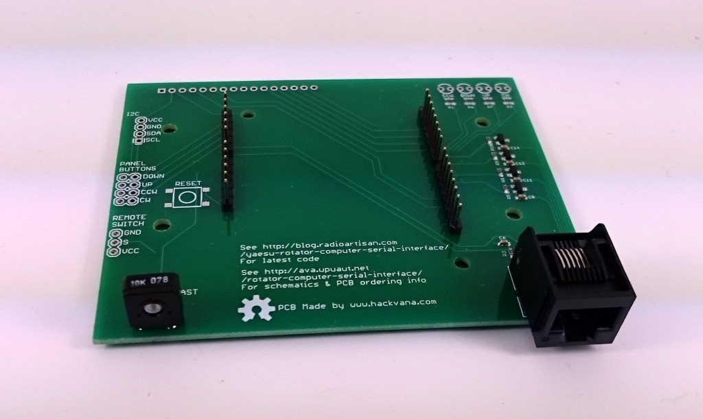
They were supplied assembled with headers, RJ45 connector, LCD brightness pot, all capacitors, resistors and transistors soldered up. You don’t get the LCD, switches, LED’s or a case of course! The PCB is designed to fit into a Hammond 1598BSGYPB enclosure (Farnell 1426554). Personally I don’t use switches but these are suitable : Multicomp Momentary PTM

Scan131

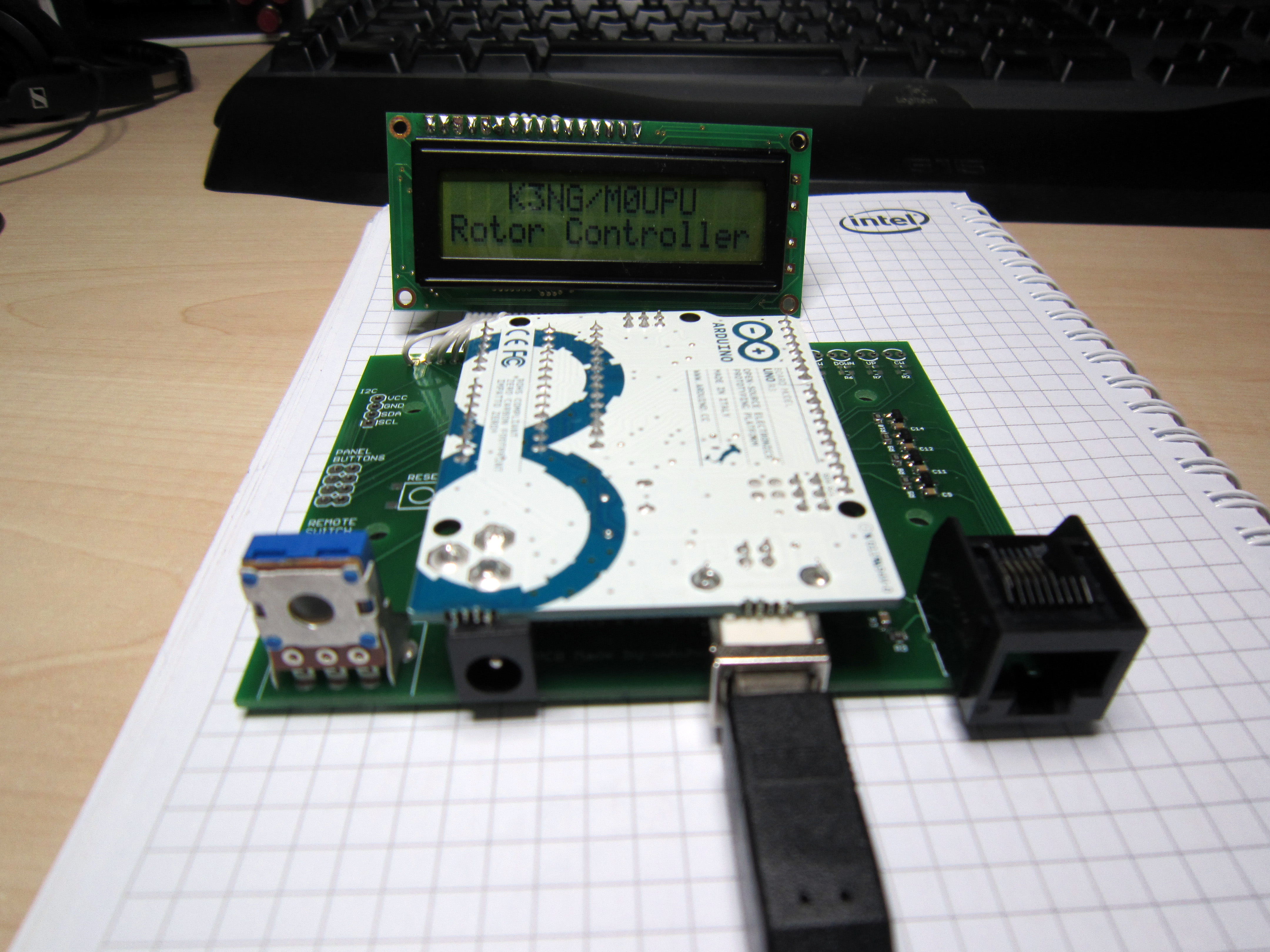
Here it is with an Uno installed :
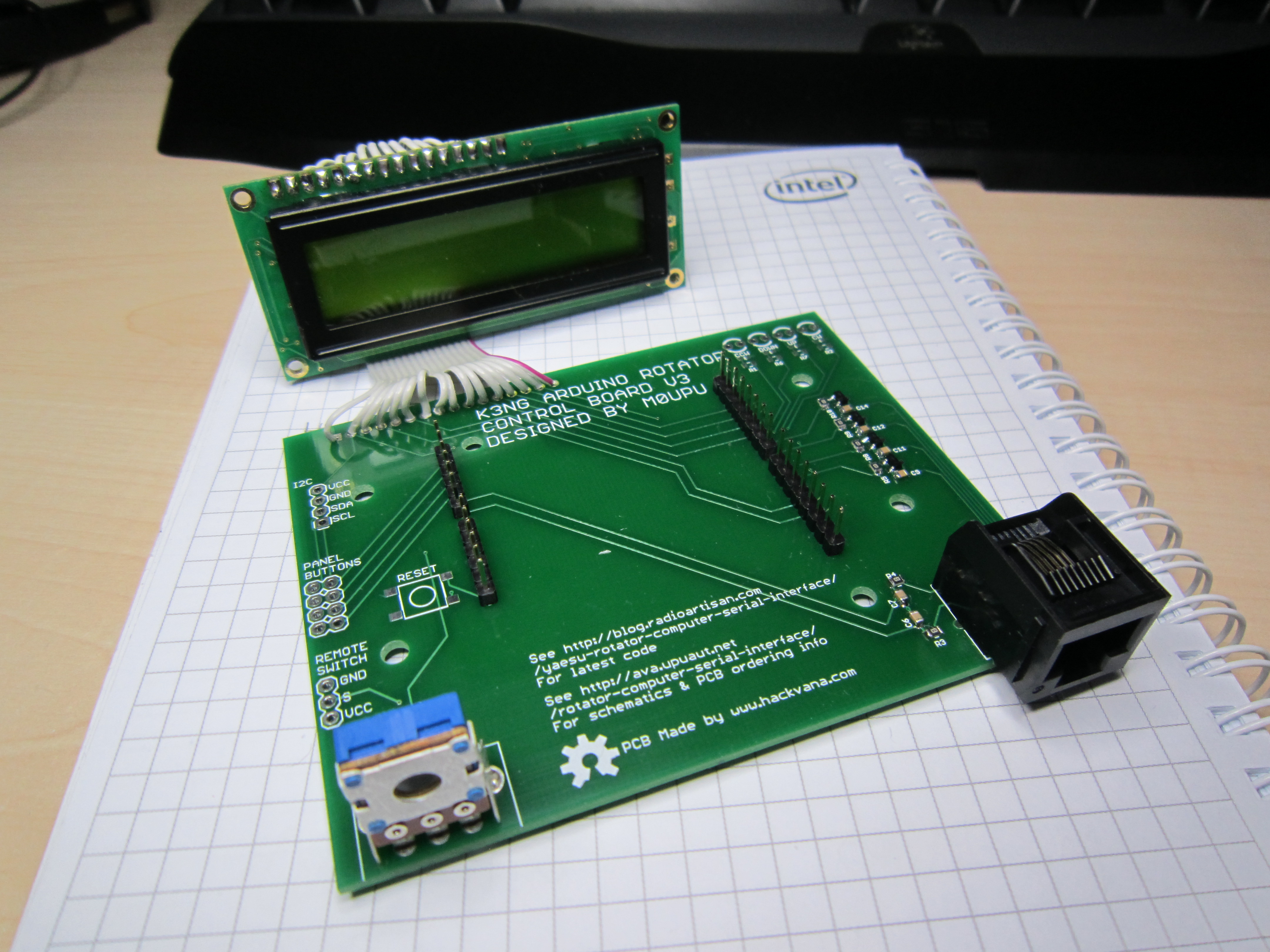
IMG_1735

And without :

IMG_1738

Update 29/05/2017 :

We are no longer making this board. It was the last board we made by hand and we no longer have the resources to do this. Unfortunately its not viable at the price to get this board made externally therefore we are discontinuing it.

Update 05/05/2013 :

I’ve sold out of the first two batches of these rotator boards so I’ve placed an order for some new ones which should be delivered before the end of May. We took the opportunity to add a few improvements to the PCB. Its still based round the concept of plugging an Arduino Uno or Duemilanove in upside down as per the post below. Additionally we added the following improvements :

1/ LCD back light is linked to a PWM port so you can adjust the LCD back light brightness via code.
2/ Reset switch added.
3/ Added a remote power switch port (I use this to power a relay to turn the controller on see http://ava.upuaut.net/?p=461
4/ Broke out the I2C Ports
5/ Added LED indicators for the axis activations.
6/ Redesigned the board to accommodate changes.

download
As before I plan to offer this PCB with the headers (RJ45 for rotator connection, Arduino headers and back light dimming resistor) and the switching circuits pre-assembled for about £25 including delivery (will confirm in the next few weeks).

You will need to supply reset switch/LED/LCD if you require these. Personally I use https://www.sparkfun.com/products/709 for the LCD.

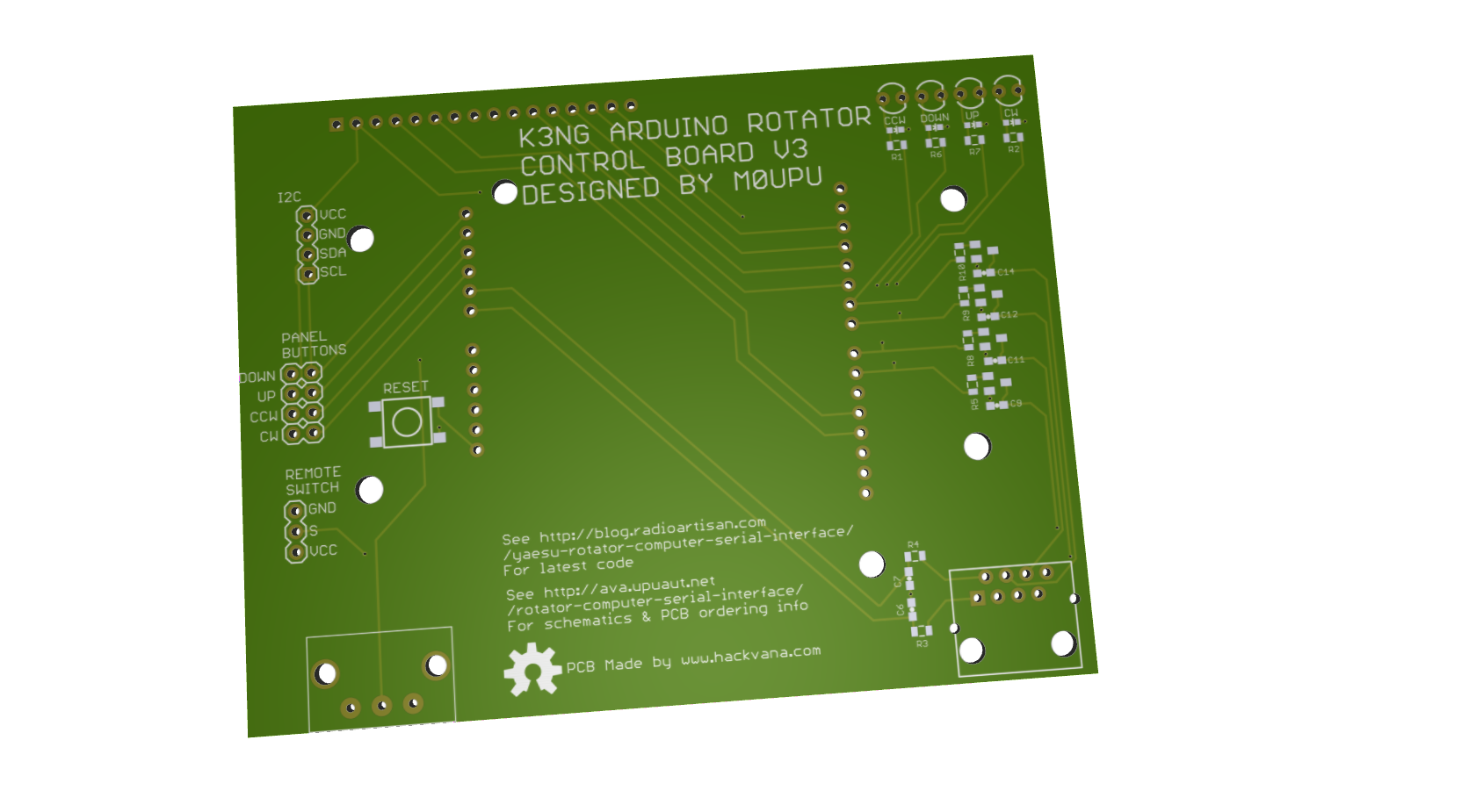
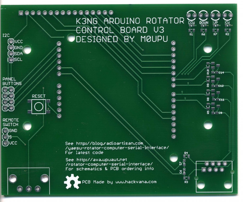
This design has been released as open source the schematic is available for download here : K3NG Rotator Interface V3, the Cadsoft Eagle files here : K3NG Rotator Interface V3. Using the schematic and this image :

standardmod
You should be able to wire a cable to match your particular rotator controller.

Original Article :

Given my ideal location for tracking on top of a hill I decided last year to beef up the Watson Collinear antenna I was using to a yagi. The only issue with this is the yagi antenna is directional and needs to be pointed at the target. To facilitate this I purchased a Yaesu G-5500 Elevation-Azimuth Rotator unit. This comes with a great controller that has a port on the back to plug in the optional GS-232A controller.

The only downside is the controller is a few hundred quid which given it can be emulated with an Arduino seemed a little bit excessive. Having spent a while searching round the web I came across K3NG’s Arduino Rotator Serial Interface which was by far and away the most complete code I’ve seen.

These days making PCB’s is so cheap thanks to Mitch at Hackvana I decided to make a board for the rotator controller hardware. Initially I was going to make a custom Arduino board with AVR on it etc but then I decided to make it easy and just put a header on there so you could plug an Arduino Uno/Duemilanove on there. This instantly gives you power, the serial interface and is replaceable quite easily.

For the other components I used surface mount 0805 components and transistors. Connection to the rotator was via a CAT5 socket. The large pot on the left is to adjust the screen brightness. The header at the back is to connect an LCD too and there are 4 headers for physical up/down/left/right switches on there.

The Arduino goes in upside down :

Then the LCD plugs in :

Finally it was designed to go in a Hammond enclosure :

Add a 3D printed front bezel :

And voila a nice tidy interface for the controller that costs a damn sight less than the proper Yaesu thing. Now use K3NG’s wonderful code at http://radioartisan.wordpress.com/yaesu-rotator-computer-serial-interface/ to get it up and working.

I’ve released this board as Open Hardware so you are free to use it as you see fit. The Eagle CAD files are here : K3NG Rotator Interface V2

Bill of Materials for the board as follows :

Resistors : all 0805 1K Farnell 9332383
Capacitors : all 0805 0.1µF Farnell 1759143
Transistors : all MMBT2222A Farnell 9846700
RJ45 Jack : TE CONNECTIVITY 3-5338556-1 Farnell 2059819
Pot : TE CONNECTIVITY / CITEC 5350500107 Farnell 1174451
Header : Just buy strips of 1 row 2.54mm pitch  header i.e Multicomp MC34743 Farnell 1593425
Case : Hammond 1598BSGYPBK Farnell 1426554

Just a quick warning I did originally intend to have the ICSP header broken out so you can program it via this but I didn’t have my spatial awareness hat on when I made the board and the lines are inverted so as it stands the ICSP break out isn’t usable (unless you plug it in from the rear of the board). This won’t affect you programming the Arduino as normal via the USB.
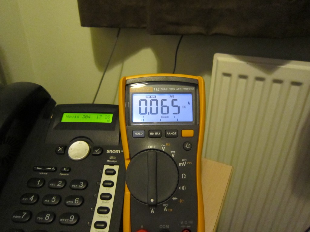
Run time on a single AA battery

…is 13 hours in a warm room :

Pico payload needs a pico container

Behold the balls!

There is no point making a 4g payload then wrapping it in 100g of payload. I theory I could just throw it in a bubble wrap bag and have done with it however as this is its first launch I decided to encase the lot in a 10cm polystyrene ball.

Using a hot wire cutter I sliced the top off the ball. This would be the antenna section :

With a little coax, some single core wire, some drinking straws and hot glue an antenna was created. Next the payload section, another slice was made in the remaining call with the hot wire cutter :

Finally some hollows were made for the battery and tracker board :

Finally the remaining top bit will have a straw through it for attaching to balloon/parachute, I’ll paint it pink tonight and report back !

Run time testing pAVAR6

Having given up on getting power saving code for the moment as we may have a launch slot this week I’ve decided to check how long the board will run for on a single AA Energizer Lithium. Having gingerly soldered some wires to one ( scratch with a fibre glass pencil, a dab of flux and as little time as possible with the iron) I’ve put the module on test. I’m guessing based on previous testing of the AAA on uAVA it should do about 12-13 hours. I will report back!

New boards pAVA Rev6

The uAVA board was a great sucess proving the concept of the smaller layout with the boost power however it was a bit of a slap dash design and the boost circuit wasn’t great. However it did successfully prove the concept and has flown on a number of flights. Dave actually flew the pAVA board on his 5th Scouts mission then tried to fly it back to me on a Pico balloon.

Didn’t do bad either it got to the Peak District before it quite literally ran out of gas. It also proved quite categorically the chip antennas work really well. The board would run from a single AAA for about four and half hours with no power saving code. We did test power saving but the code isn’t reliable and on an attempt to fly the uAVA board on Dave’s BEAR launch with power saving the GPS locked up. Fortunately it was recovered as it was attached to another payload.

I’ll keep working on the power saving as if it worked 6.5 hours from a single AAA is very possible. Anyway onward, in an attempt to push the power consumption down even further and reduce the size and weight even more I started working on a new revision of the pAVA board. I decided to make this board have the ability to run at both 3.3V and at 1.8V to reduce the power consumption even further.

After a number of redesigns pAVA Rev6 (catchy huh ?) was born. Combining the usual ATMega328, RFM22B and the uBLOX MAX6 with a TPS61201DRC boost converter has resulted in a very small board weighting in at 4 grams without antenna. The board can run at 3.3V (with a TPS61201DRC and a 8Mhz crystal) or at 1.8V (with a TPS61200DRC and a 4Mhz crystal). To facilitate 3.3V usage a single R0 bridges the voltage divider for the adjustable version.

The TPS6120XDRC has a PowerPAD(TM) under it which it uses to dissipate the power, not having a reflow oven I put a via through the PCB to facilitate soldering from the underside. Its quite a tough module to solder by hand, the 10 pin QFN module is only 3mm x 3mm.

Shown above , top board is using a low profile HC49 crystal and has headers on (this is my development board), below it is a 3.3V version with no headers and the Abracon ABM03 crystal weighing in at 4g.

The board also has pins A0 to A5 broken out for future things.

Here is a pic of it next to an SD card for scale :